
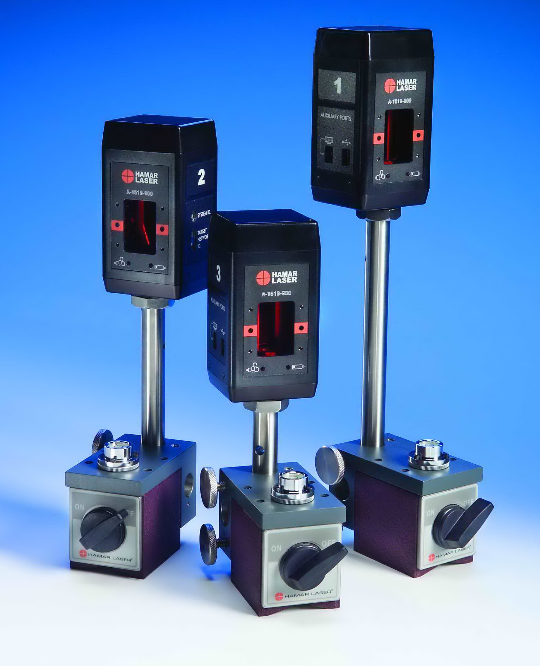
Description
The A-1519-2.4XBE 2-Axis, Wireless Target has a very high resolution of .00002 in. (0.0005 mm) and accuracy with a large measuring range of ±.55 (±14 mm). The A-1519-2.4XBE-2X is specially configured to be used with our A-1511-A Wand Bore Fixture and with our L-702SP/L-703/L-705/L-706/L-708 beam lasers for doing half-bore alignment checks on large bore applications such as steam and gas turbines. It operates with Xbee® radio technology that allows wireless communication with up to 99 targets at the same time by using a robust, frequency-hopping radio technology. The data for these targets updates in real time and is sent either to our R-1307-2.4XBE Readout, R-1308 Readout, R-1357-2.4XBE PDA Display or a Windows®-based laptop or tablet.
Applications
- Caster Segments
- Gas turbines Half-Bore Alignment
- Gantry & Spar Mills
- Horizontal Boring Mills
- Horizontal & Vertical Machining Centers
- Injection Molding Machines
- Large-Bed Lathes
- Machine Bed Leveling
- Presses
- Roll Alignment
- Steam turbine Half-Bore Alignment
- VTL’s
Features
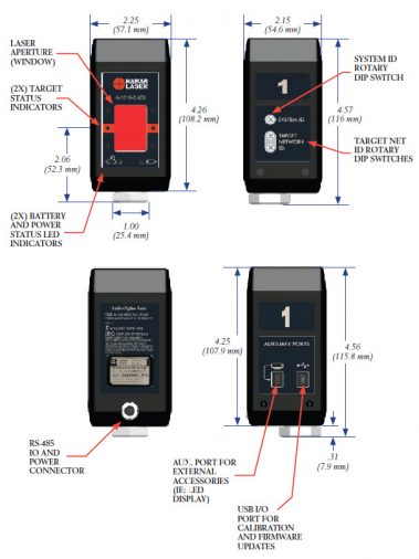
- Operate in both Single and Dual-Axis Modes (depending on the readout used) and use XBee® radio technology:
- Single-Axis Scanning Mode – used with Hamar Laser’s continuously sweeping lasers (L-702SP & L-730/L-740 series) for measuring the flatness, straightness, squareness and parallelism of both machine tools and rolls.
- Dual-Axis Mode – used to detect non-rotating laser beams in such applications as gas and steam turbine half-bore alignment.
- Features 2-axis, super-linear, position-sensitive detectors with automatic background-light correction for extremely accurate readings.
- Several options are available to display the target data:
- The R-1357-2.4XBE Rugged PDA display
- The R-1307-2.4XBE Readout for 2 A-1519 targets
- R-1307W-2.4XBE Readout for 2 A-1519 targets
- R-1308 Single-Axis Readout
- A-910-2.4XBE Computer Interface for use on a laptop
- Resolution of .00002 in. (0.0005 mm) and a measuring range of ± .55 in. (± 14 mm).
- Linearized accuracy of ± .00015 in. (±0.0038 mm).
- Targets can be used out to 100 feet (30.5 mm) from the laser.
- The A-1519 package include the target, a magnetic base and three insert posts: 6.25 in., 4 in., and 2 in. (158.8 mm, 101.6 mm and 50.8 mm) for coarse height adjustment.
- Completely automatic on/off operation with no switches, wires or connections. The target activates when the laser beam sweeps across the target cell and flashing target LEDs provide immediate “on/off target” status.
- Powered by 2 internal lithium-ion batteries for up to 11.5 hours of continuous use. Comes with AC adapter/charger, low battery and charging indicators.
- Targets can also be charged with the optional A-1519CS-4 Charging Station that charges up to 4 targets simultaneously.
- Communication working distance (PDA/PC Base Station to target) is 150 feet (45 m) or greater.
Specifications
Sensor Resolution
.00002 in. (0.0005 mm)
Linearized Accuracy
±.00015 in. (±0.0038 mm) over central 80% of PSD
Measuring Range
± .55 in. (± 14 mm)
Detector Size/Type:
2-Axis PSD, 1.30 x 5.1 in. (33 x 13 mm)
Radio Frequency
2.4 GHz, DSSS (Direct Sequence Spread Spectrum)
Transmit Power
+8dBm (6.3mW)
Indoor Range
133 feet (40 m)
Battery Life:
11.5 hours continuous duty
Operating Temperature:
35° F to 140° F (2° C to 60° C)
Operating Range:
100 feet (30 m) from laser to target
Measuring Target Weight:
14 oz (0.40 kg)
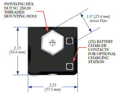
Magnetic Base Size:
2.00 W x 2.53 H x 3.55 in. D (w/o T-screw)
(50.8 x 64.2 x 105.2 mm (w/o handle )
(50.8 x 64.2 x 105.2 mm (w/o handle )
Magnetic Base Weight:
2.78 lb (1.26 kg)
Certification
FCC ID: MCQ-XBEE3. This device complies with FCC rules, Part 15
CE: Complies with ETSI
IC ID: 1846A-XBEE3 (Canada)
RCM/R-NZ (Australia/New Zealand)
ANATEL 06329-18-01209 (Brazil)
TELEC [R] 210-119309 (Japan)
CE: Complies with ETSI
IC ID: 1846A-XBEE3 (Canada)
RCM/R-NZ (Australia/New Zealand)
ANATEL 06329-18-01209 (Brazil)
TELEC [R] 210-119309 (Japan)
Drawings
- Call Us: +1-203-730-4600
- Email: sales@hamarlaser.com
- Website: www.hamarlaser.com