
Resource
Center
Welcome to the Hamar Laser Resource Center; your one stop for videos, downloads, case studies and more. With over 50 years of laser alignment experience our knowledge is vast.
Choose Resource
Hamar Laser Demo Videos
Our channel for demo videos, tips and system specific video bytes.
Alignment Systems for Geometry – Other Videos
L-743 3D Video – Part 5 – Table Flatness Check with Plane5
L-743 Triple Scan® Laser – How to Check Guideway Flatness & Parallelism
L-702SP 5-Axis Machine Tool & Spindle Alignment Laser – Part 1 Features and Benefits
Hamar Laser Training Videos
Our channel for system specific and support training videos
L-730/L-740 Lasers Alignment Basics: Laser Setup
L-730/L-740 Lasers – Application Training Videos
L-705/L-706/L-708 Bore Lasers – Application Training Videos
L-700 Spindle Laser – How to Align Lathes & Turning Centers
How to Align Lathes & Turning Centers using the L-700 Spindle Laser
L-742/732 Dual Scan® Roll Alignment – Part 1 Features and Specs
A
Arc Second
A measure of angle equal to 1/3600th of a degree or .00006″/ft. (0.005 mm/m)
Axial
Located on, around, or moving along an axis.
Axis of Rotation (AOR)
A straight line about which a body or geometric object rotates. The axis of rotation of a spindle is the centerline around which the chuck or tool holder rotates.
B
Bore Center Error (BCE)
A measure of the offset of a bore’s center from a reference bore’s center.
Buck-In (Bucked-In, Bucking-In)
Aligning a laser plane or laser line to be parallel to a surface, a set of bores, a rotating axis or line of motion being measured. Three reference points on a surface are required to buck-in a laser plane to that surface. Two reference points on a line are needed to buck-in a straight-line laser to a that line (i.e., centerline).
Buttock Line
An aerospace term used to describe a reference line that runs along the length or the longitudinal axis of the aircraft. An aircraft contains several buttock-line sections.
C
Catenary Sag
The curve theoretically formed by a perfectly flexible, uniformly dense cable that is not capable of being stretched further and is suspended from its endpoints. It is a measure of how much the elevation of a cable drops between its 2 endpoints due to gravity.
Colinear
A single, straight line that is lying on and parallel to a second single straight line.
Concentric
Of or denoting circles, arcs, or other shapes which share the same center, the larger often completely surrounding the smaller
Continuously Rotating Laser Planes
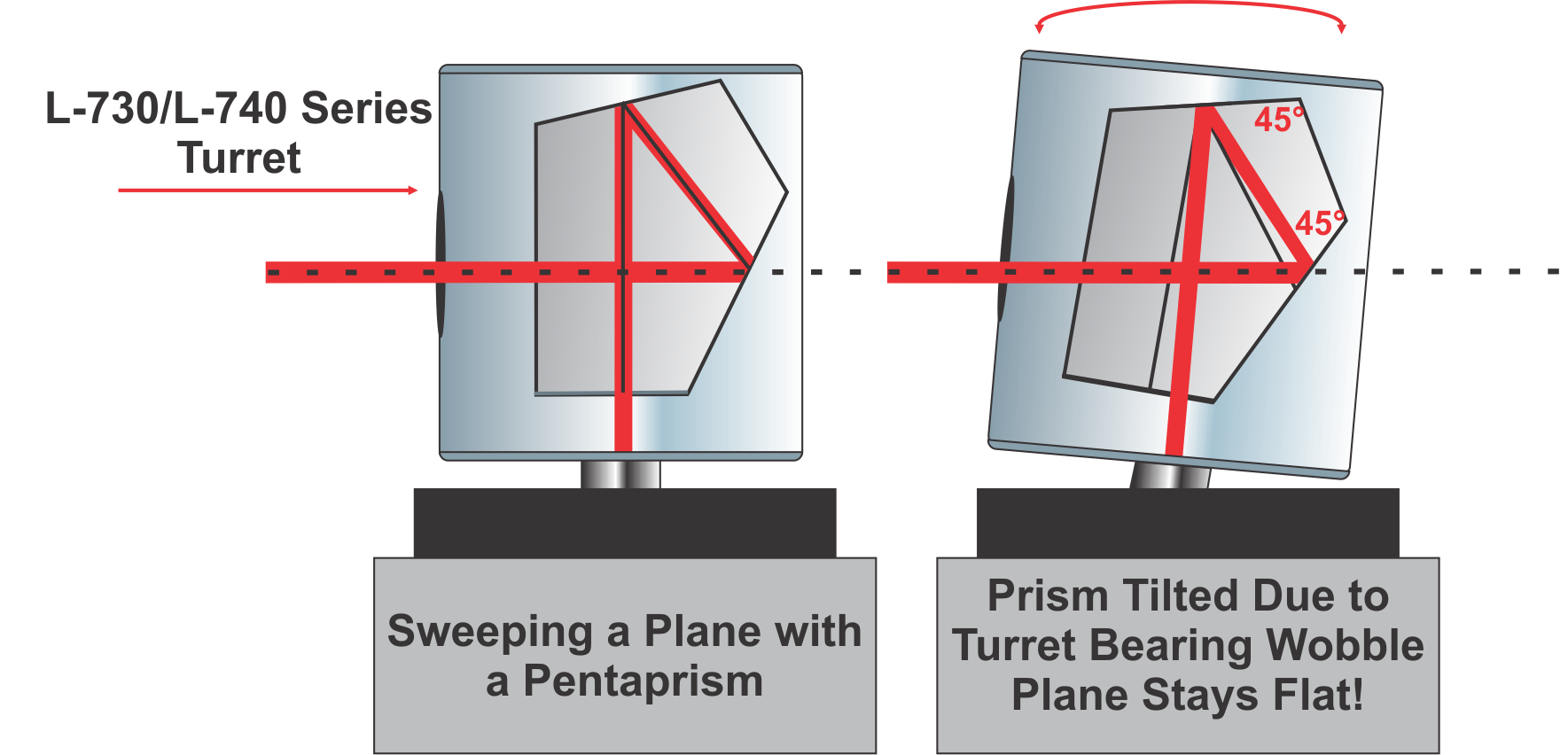
Laser planes that are generated by an automatically rotating spindle containing a pentaprism. Sometimes called a “sweep” laser.
D
Datum
A reference used as a basis for calculating or measuring. See Reference Points.
F
Flashing
A quality problem in plastic parts that occurs when the molds do not contact each other in a parallel manner, which causes excess plastic to build up on the part.
Flatness
The state of having a smooth, even, level horizontal surface without slope, tilt, or curvature.
H
He-Ne Laser
Helium Neon laser is a type of laser that is usually used in interferometry. It is not as spatially stable as diode lasers and usually requires 1 hour warm up.
I
Interferometer
An instrument that measures changes in the linear position (distance) of a machine’s axis. This is accomplished by counting or displaying interference fringes created by a light source of known wavelength. It is typically used to calibrate the scales of machine tools. It can also be used to measure machine geometry but it can only do so 1 axis at a time and cannot be used to re-align the axis since the data does not update in real time.
L
Laser Planes
An automatically rotating laser beam that sweeps a plane of light used to measure surfaces and lines of motion of machine tools. Laser planes measure more alignment parameters with each setup than a laser beam. For example, to measure a surface plate for flatness, it takes 1 setup with a laser plane and 8 setups for a laser beam. Difficult measurements such as rail twist or vertical roll of a machine tool axis are extremely easy to measure with a laser plane but nearly impossible with a laser beam.
Least Squares, Best-Fit Algorithm
The least-squares, best-fit algorithm is a mathematical function that finds the slope of a line (or the X-Y slopes of a plane) that “best fits” a set of data, usually a set of flatness/straightness data. This function is used by our software when we want to measure squareness (or parallelism) of surfaces or lines of motion (axes), since the best way to determine squareness or parallelism between surfaces (or lines of motion) is to compare the slopes of the best-fit lines for each set of data.
Here is the formal definition of the least-squares, best fit function and here is an image showing an example from our Machine-Tool Geometry software showing of a graph of a linear axis flatness data with the least-squares, best-fit line drawn through the data.
Level
Having a flat, smooth surface as characterized by using gravity as a reference. Being on a horizontal plane parallel to earth’s surface
Live/Real Time Data
Target readings displayed on a computer or readout that update automatically as adjustments are made to the point on a machine that is being measured and aligned. This allows the user to watch the machine move into alignment.
N
NORMIN Method
The NORMIN method was developed by Hamar Laser to compensate for laser and/or target mounting errors in bore or spindle work. The word is a contraction of “NORMal and INverted.”
The NORMIN procedure is used to make a laser beam parallel to an axis of rotation in spindle applications or to calculate laser centering errors in bore applications. For spindle applications, it works like this: a laser or fixture holding the laser is placed in a spindle in the normal position (12 o’clock). The laser is turned on and the readings are recorded. Next, the laser is rotated 180°.
O
Offset Centerline
Usually used in roll alignment applications. An offset centerline is a line established to the side of a process mill that is parallel to the machine’s centerline. It is used as a reference to measure roll parallelism.
1 Arc Second
A measure of angle equal to 1/3600th of a degree or 0.00006″/ft. (0.005 mm/M).
Optics
Theodolites, transits, optical borescopes or any other measuring instrument using optical instruments to measure levelness and straightness.
P
Parallelism
2 or more lines or planes, extending in the same direction and everywhere are equidistant from each other. Planes and lines are said to be parallel to each other if they never meet when projected out into infinity.
PDA Display
Used as a target readout in the R-1356-2.4ZB
Pentaprism
A 5-sided prism that accepts a laser beam in one side and projects it at a precise 90. Click here to see an example.
Pitch
As a linear axis travels along the Y axis, the pitch angle of the axis is a measure of how much the bearing or carriage tilts in angle, at a given location, about (around) the X axis (i.e. in the axis perpendicular to the axis of travel), as it traverses along a set of guideways.
Point-and-Shoot Lasers
A type of laser alignment system that does NOT automatically rotate. To take measurements the user has to walk back and forth from the laser to the target to precisely point the laser beam to a target location to get a measurement. Each time the target is moved, the user has to precisely point the laser to the target.
Position Sensing Detector (PSD)
An analog device that uses a piece of silicon to detects the center of energy of the laser beam . The analog signal represents the position of the laser beam and is turned into a digital value by the use of signal processing electronics.
R
Radial
Having or marked by parts radiating from a common center. Moving or directed along a radius and perpendicular to an axial direction.
Reference Points
Points chosen on a surface or in a bore that represent the starting point (reference) from which all other points on the surface or in a bore will be compared. Also referred to as a datum. For bore, spindle and rotating shaft applications 2 reference points are needed to establish a datum. For surfaces, 3 reference points are needed to establish a datum.
Roll
As a linear axis travels along the Y axis, the roll angle of the axis is a measure of how much the bearing or carriage tilts in angle, at a given location, about (around) the Y axis (i.e. in the axis parallel to the axis of travel), as it traverses along a set of guideways.
S
Self-Centering Target
A 2-axis bore target that automatically centers itself in a bore with no moving parts.
Squareness (Perpendicularity)
2 intersecting lines or planes are said to be square to each other if the angle between them is exactly 90 degrees. The measurement of squareness is typically done by using an artifact, such as a piece of granite, that has 2 surfaces that are known to be square to each other to a high degree of accuracy and measuring deviation of a line of motion or surface relative to the artifact.
Another way to measure squareness is to use 2 laser planes (L-732, L-742, L-733, L-743) that are known to be perpendicular to each other and aligning 1 plane to a datum, such as a line of motion on a machine tool, and using the second plane to measure a second line of motion.
Station plane
An aerospace term used to describe a reference plane that runs perpendicular to the buttock lines of the aircraft. An aircraft contains several station planes. They are often also referred to as bulkhead-section planes.
Straightness
The state of having a line that extends continuously in the same direction without curving.
T
Target
A measuring device that detects the position of a laser beam or laser plane. Targets can measure in 1 axis (used with scan planes), 2 axes (used with straight beams to measure H&V center values) and 4 axes (used with straight beams H&V Center, H&V angle)
Target centering error (TCE)
Calculated by adding the normal and inverted readings and dividing the result by 2. TCE is a measure of how far from a bore center the target’s center actually is. Can be used to adjust raw readings to find true bore centering error (BCE).
Top Dead Center Method
Top Dead Center (TDC) method is used when measuring the parallelism or levelness of rolls. With the target facing the laser, the roll is rotated slightly back and forth until the highest point is determined, which is the top dead center of the roll – see here. This should be used when tight tolerances are needed or when it is difficult to determine if the target is near top dead center, usually when measuring vertical rolls.
Can also be called Arc Method or Sweeping Through the Arc Method
W
Waterline
An aerospace term used to describe a horizontal reference plane that runs throughout the aircraft. Many surfaces and interior features are made parallel to this reference plane.
Y
Yaw
As a linear axis travels along the Y axis, the yaw angle of the axis is a measure of how much the bearing or carriage tilts in angle, at a given location, about (around) the Z axis (i.e. in an axis perpendicular to the Y and Z axes), as it traverses along a set of guideways.
We’ve been in business for 51 years which means we have seen it all. During that time, we have aligned almost every application, and as a result, have the widest laser alignment product offering in the marketplace today. Below you will find a very small sample of some of the stories our customers have told us over the years. The list may be small but the number of customers who have successfully profited from using our lasers is too numerous to publish.
-
Case Study: Hi-Tech Compressor & Pump Products
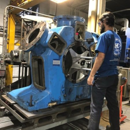 Hi-Tech Compressor and Pump Products, based in Tullytown, Pennsylvania, had just taken on a challenging compressor reconditioning project and was trying to sort out how to QC the alignment. Known for providing expert, responsive service, the company specializes in refurbishing reciprocating compressors and industrial pumps, and has a reputation for high quality work.
Don Weidemann, Hi-Tech’s Director of Quality, had to be certain the tolerances of the compressor bearing bores were on spec, but his customized dial indicator setup was not providing consistent results. The company’s reputation was on the line, the tolerances were very tight and his measurements had to be repeatable and reliable. After careful research, he found the answer in the L-702SP, a new laser alignment system made by Hamar Laser Instruments in Danbury, Connecticut.
Read “Fair and Square: Using lasers to nail critical QC checks on compressors,” published in CompressorTECH2 (digital magazine) and get the article reprint (downloadable PDF).
From the get-go, Hi-Tech Compressor and Pump Products worked with Hamar Laser Instruments to develop the procedures to check the large multi-throw compressor frames and align their shaft-bearing bores to a boring mill for re-machining. Hi-Tech used Hamar Laser’s versatile L-702SP Scan Laser with Plumb Beam, along with Hamar’s laser self-centering targets, beam translator, bore adapters and readout.
See the illustrated step-by-step alignment procedures:
“Using Hamar’s L-702SP on Compressors”Want more info?
- Contact us at sales@hamarlaser.com or call 203-730-4600.
- Request a quote / demo.
-
Case Study: Laser Alignment in Sawmills
Adjusting straightness of sharp chain transport track thru primary breakdown center with the L-743 Ultra-Precision Triple Scan laser alignment system from Hamar Laser Instruments Ultra-accurate scanning lasers can boost recovery and profits.
Putting aside conventional methods like optical theodolites and wire, a steadily growing number of sawmills are aligning their machinery with scanning lasers. These systems offer greater ease-of-use, higher accuracy and excellent repeatability over older methods and so-called “pointing” lasers, and can produce significant gains in recovery.
For several years now, David Reed, Sr., founder of Cutting Edge Tooling, LLC, has been implementing laser alignment at sawmills—and winning converts. Based in Russellville, Ark., Reed’s company offers precision machining and alignment services for the forest products industry, and he has been using ultra-accurate scanning lasers to help sawmills align machinery faster and more precisely, improving recovery in the process.
Reed uses laser alignment systems from Hamar Laser Instruments, Inc., headquartered in Danbury, Conn., to align most kinds of sawmill machinery, including sharp chain machine centers and other equipment. He serves corporate and independent sawmills throughout the U.S. and his regular customers include many of the leading names in the industry.
Read the 3-page published case study on page 32 of the October 2019 issue of Timber Processing (digital magazine) and get the article reprint (downloadable PDF).
Want more info?
Read about the L-743 Ultra-Precision Triple Scan® Laser Alignment System on the Sawmills page of our website.
Contact us at sales@hamarlaser.com or call 203-730-4600.
Request a quote / demo.
-
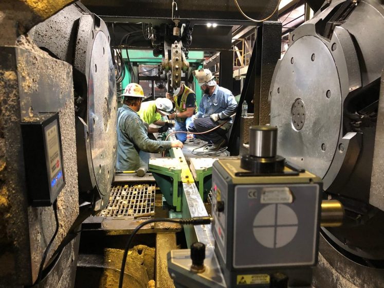
Lasers Solve Alignment Problems for Dofasco’s Casting Machines
With lasers manufactured by Hamar Laser Instruments, innovative Canadian steelmaker Dofasco pioneered a continuous caster laser alignment system that achieved significant segment repair cost and time savings and resulted in increased segment life and improved as-cast slab quality. A subsidiary of ArcelorMittal, the world’s largest steel and mining company, Dofasco operates two continuous casting machines. High accuracy alignment is critical to meet tolerances of .002 in. (0.05 mm) and produce defect-free slabs.
When the first caster was brought on-line, Dofasco used OEM alignment stands and templates to align segment rolls to the passline and profile. This procedure, using feeler gauges, was very time consuming and a source of variability due to tradespeople’s fitting practices. It required 15 hours to complete and meeting tolerances was very difficult. Dofasco soon implemented an aligning procedure using an optical level. While an improvement, this method was also time consuming, needing 8 hours to complete, and meeting tolerances continued to be very difficult.
Within several years Dofasco had begun looking for a laser-based solution. The steelmaker turned to Hamar Laser, which implemented new alignment procedures using Hamar Laser’s L-740 Ultra-Precision Leveling Laser System, A-1530 Height Gage Target and a customized software package to align the caster segment rolls. The results achieved with the Hamar Laser system were dramatic.
Overall alignment time dropped by 87% and tolerances are met consistently. Repair times decreased more than 50%. The time required to rebuild segments was drastically reduced, and segments are now consistently rebuilt and installed with transitions well below the allowed standard of 0.12 inches. This reduced variability directly improved as-cast slab quality and segment life. Longitudinal and transverse cracking associated with misalignment was reduced to zero and segment life extended by more than 30%.
Read the entire Steel Technology article here.
-
Alcan Aluminum Switches from Optics to Lasers and Saves $250,000
By Guy Laverty, HLI Alignment Technician
Canada-based Alcan Aluminum (acquired by Rio Tinto in 2007), one of the world’s largest aluminum manufacturers, successfully used Hamar Laser’s L-723 Triple Scan® laser* to align an aluminum ingot producing machine. Before changing to lasers, Alcan had been using 2 optical systems with 4 technicians for this complex and difficult alignment, but with limited success.
Hamar Laser’s L-723 was brought in to tackle the alignment and was able to do the alignment job with only 1 system and 1 technician. The laser was able to measure 20 points for every 1 point measured by the optical system. In addition, the laser aligned the ingot forming machine to .006 in. (0.14 mm), the most accurate alignment of the machine the maintenance techs had seen to date.
In the end, using the L-723 resulted in a total time savings of 2.5 days, with a machine production value of $250,000. In addition, operators reported that the finished ingots were much straighter after the laser alignment, resulting in almost eliminating a second “shaving” operation. Needless to say, the system paid for itself in 1 day!
* The L-723 Triple Scan® Laser Alignment System that was the subject of this case study has been superseded by the L-743 Ultra-Precision Triple Scan® Laser Alignment System.
-
Universal Instruments Saves $1.5 Million in Production Costs
Source: Letter from Paul Hudec, Process Engineering Analyst, Universal Instruments Corporation
This is an update on the use of the Triple Scan® Laser Alignment System that we purchased from you. We’ve ended up using it more for process/product research and qualification than for machine tool metrology, although we do use it for both.
We did a Measurement Systems Analysis (MSA) of the system in relation to our frame, similar to the testing we did before we bought it. The analysis confirmed that the system was capable of detecting the required process and product variation (accuracy and repeatability over the required volume), keeping in mind appropriate metrology practices to control potential sources of variation such as setup, thermal error, etc.
Once the measurement system capability was established, we tested over thirty frames under different processing regimes to quantify the output of the machining processes. The intent was to see if we could eliminate an extra 4-hour machining operation. The machining test data were independently correlated with assembly test data for those frames. The end result was that we were able to eliminate the extra operation.
- Benefits/Savings: elimination of the extra machining operation resulted in 1,768 hours saved in the last five months (4,243 annualized hours) — a substantial time/dollar savings.
- Additional Capacity: these 1,768 hours (4,243 annualized) have also been gained as additional capacity for producing more product with the same resources. [Ed note: Universal was able to cancel a $1.2 million order for a new machine by freeing up this capacity.]
- Data: We were able to cost-effectively obtain data from machining and assembly operations, which we previously couldn’t do. Either we didn’t have the equipment of equivalent or better capability, or such equipment could cost 2 to more than 10 times the system that we purchased. The data obtained with the laser system, combined with simultaneous data from other instrumentation, enabled us to confirm or disprove hypotheses about manufacturing and assembly processes, and about inherent product characteristics.
The above is only one application so far. We do use the laser for machine tool characterization and find that it can be a time-saver. It’s also being used to quantify process output (product characteristics) for machining and assembly operations.
We appreciate the time you’ve spent and the service you’ve provided in helping us with this equipment.
-
Power Company in Georgia Increases Turbine Efficiency with L-705
A power company in Georgia was one of our first customers in turbine laser alignment. They originally bought an L-711 (one of our early alignment systems) in 1979 and since then have upgraded their system many times and use our lasers for all of their outages. They tell us that on the very first alignment they did with our lasers, they were able to increase the efficiency of their turbines significantly. The way they put it is that before laser alignment, the turbine rotor took 10 minutes to stop rotating after shut down but after laser alignment it took 34 minutes! They are confident that the system paid for itself in the first month of operation. This does not even count the time they saved on their outages by using lasers versus tight wire.
-
Mark IV Press Runs at Full Speed with No Adjustment Upon Initial Run
LGM Graphics
By Randy Bruce, HLI Technician
On a recent application using the L-723 Ultra-Precision Triple Scan® Laser Alignment System* and the L-740 coupling Laser we had great success installing a printing press.
The press being installed was a Hantscho Mark 16, 4 color printing press. Using the scan planes of the L-743 we made each unit from the roll stands to the folder square within .00″ to each other from end to end. We also insured each unit was on center line within .010″ from end to end (100′).
Since it was a CNC press, it can, if needed, adjust the roll automatically to be in line with the centerline of the plates. Upon start up, the press didn’t adjust any rolls, so the press was run up to half capacity (20,000 cycles per hour). After startup the press was checked for any adjustments that might be needed and none were found. The press was then increased to full capacity (40,000 cph) with no ill effects found. The installer I was working with said he had never seen a press start up as easily and on line as this one did in his 30 years in the business.
Using the L-740 coupling Laser reduced the drive shaft alignment from 3 days to 5 hours and the whole alignment took approximately 5 days, with a much higher accuracy than optics or wire alignment could ever achieve.
The installer’s comment (John Crumm, Litho Repair Service) after seeing this system work was that “If your press has not been laser aligned, then your press has not been aligned!”
* The L-723 Triple Scan® Laser Alignment System that was the subject of this case study has been superseded by the L-743 Ultra-Precision Triple Scan® Laser Alignment System.
-
Machine Scrapping Uses Laser Technology to Improve Accuracy
Combining New Technology with Old Art Form for Improved Accuracy
Source: Powertrain Connection — A UAW Plant Newsletter
Old methods and new technology are being combined at Plant #3’s Rebuild Area in such a way that greater accuracy, more dependability, and a faster rebuild time is realized from the machinery taken there.
Randy Bruce, Fixture Repairman, and Bob Jones, Machine Repair, are reviving the old method of “scraping” (which has not been a part of the educational training for new Tradesmen for some time now) and combining it with the technology of surface and spindle lasers to come up with a system that brings machine tolerances within limits that are more than just acceptable. “In the past,” explains Bob Jones “if a machine was set up and its tolerances were within the outside parameters, and it was set level, the machine would be run and everyone was happy. But tool-life would be reduced because not all planes were looked at to find that level. Today, with the lasers, we can not only find out if a machine is level, we can check every surface for inclinations, parallels, perpendiculars, etc. Our accuracy is within tens of thousandths. This improves the accuracy of machining and increases the life of tools.”
“The art of scraping,” says Bob Jones “is one that has been passed on by some of the old-time Journeymen to Apprentices or EITs that have worked with them. It is not a skill that is taught in the classroom. Grinding seems to be the preferred method for many, but scraping is more precise and when used in conjunction with lasers, it gives a much better fit for parts. These methods are not being used in the industry today.”
Bob Jones and Bruce are currently rebuilding a Precision Surface Grinder from Building 40’s Tool Room. The machine will be rebuilt (on balance time) from the ground up taking special care to ensure that the surface of each part fits perfectly with other surfaces. Bob Jones says that by using laser technology, there will be approximately a 40% time savings over other methods that require constant leveling and releveling to double check accuracy.
Bruce adds, “Because of the success we have had, we’ve gone into the shop of an outside vendor with our lasers and verified the accuracy of their work (when they are doing work for us). Our goal is to prove that we can do the work faster, more accurately, and cheaper by keeping it in-house instead of using outside vendors. I believe that we are doing that.”
George Hall, Maintenance General Supervisor, fully supports the work that Jones and Bruce are doing and agrees with their goal. “In Powertrain, Union and Management are working together to try to reduce subcontracting of work that our employees can do. Jones and Bruce are doing an excellent job and with the help of employees like them, this is one phase of the business that we are proving we can do competitively with improved quality in-house.”
“As I’ve said many times in the past,” says J. Hill, Skilled Trades Shop Committeeman, “if our Skilled Tradesmen are provided with the resources and the opportunity, they can make significant contributions in the cost and quality arenas — and this insures their own job security.”
-
Lasers Help Reduce Mark IV Press Warm Up Periods
Source: LGM Graphics, Inc. Company Newsletter
“The most efficient use of paper has become increasingly imperative as paper prices rise and sensitivity to environmental issues grow. As LGM’s environmental watchdog, the control and management of our paper stock is of considerable interest to me.” — Enviro Eddy, Environmental Watchdog, LGM Graphics Inc.
The sound is a piercing 90 decibels of mechanized activity — the sound of the Mark IV Press. Another magazine is rolling off the press and in the time it takes to turn my head, the signatures are cut, folded, and packed on skids ready for the bindery process. The sounds all but drown Bill’s voice as he describes the action that is taking place all around us.
I’m Enviro Eddy. I’m in the press room at LGM Graphics and about to learn from Bill Goralchuk, Web and Engineering Manager, the steps that have been and are being taken to gain control over paper consumed in the printing process. The most efficient use of paper has become increasingly imperative as paper prices rise and sensitivity to environmental issues grow. As LGM’s environmental watchdog, the control and management of our paper stock is of considerable interest to me.
Numerous factors come into play as we study the problem of paper waste. At the start of each job, the press is “webbed” up and the make ready is begun. As the paper is pulled through the press, the crew adjusts the color, water register, folding and many other areas and control the printing process. So, until the product is ready to save on skids, what is being produced? You guessed it; the less waster there is in paper, ink and labor.
Since the purchase of the Mark IV in 1988, our make ready and run waste has been significantly reduced. And how did we do this? I thought you would never ask.
Color setting time has been reduced through the use of the state-of-the-art scanning and computer-based press adjustments. Register is automatically adjusted by stroke cameras that use targets on the web to manipulate the paper and cylinders. The job is then completed by a computer-controlled folder.
Water composition plays a role in printing jobs. The characteristics of a city’s water supply can vary depending on the season and what the city puts into the water, to keep it safe for the population it serves. These fluctuations in water composition cause problems with color production, and again, when the colors change within a job, the job is unacceptable, that translates into paper waste. Although Winnipeg’s water supply is far from being the worst for impurities, it was causing a degree of difficulty. To counteract this problem LGM installed a reverse osmosis filtration system, which cleans our water supply, eliminating all but 2% of the impurities. This has further reduced our make ready waste, to the point where impurities in the water are no longer a problem.
The amount of paper that moves through modern presses is phenomenal — in the area of 14 million pounds annually. Of course, with no method of control in place, waste would also be phenomenal.
Arriving at an efficient method of managing and controlling the amount of waste paper coming off the presses has been a long and arduous task for Bill Goralchuk. But, step by step, the battle of waste paper is being won. It actually began as far back as 1982 when an attempt was made to “try to identify waste from records.” Bill, with consultant Jack Russel who had expertise in the area of waste management, made an effort to develop an accurate press count system.
After testing several different systems LGM chose the Toledo Seale Company technology, combined this with input from Bill and the computer expertise of Mind Computers (Brad Fry and Neil Stern) and created a system customized to our particular requirements. This system, using QNX Windows-based software developed in Ottawa, now provides us with much more information. It has eliminated under and over-production on jobs, and we know how much waste there is on a job — the current average is around 2%. The monitor indicates the quantity to be printed, the quantity that has already been printed, and indicates the percentage of waste produced at each moment of the press run. An added feature of the systems includes a preventative maintenance program. The monitor indicates at what point the press needs grease and oil.
By the time this article is published, LGM’s new Hantscho Mark 16 Press will be operational. With the introduction of our new 4 million dollar press we will be moving to the 50-inch-wide rolls of paper. This will further reduce waste paper by cutting down on the number of splices and will reduce the amount of space required for storage of inventory by 30-40%. To solve the problem of mis-alignment a new technique called “laser alignment” [HLI’s L-743 Ultra-Precision Triple Scan® Laser Alignment System*] is being used for the first time with the equipment. This will refine printing accuracy to within 1/1000th of an inch as opposed to the present 5 to 10/1000th of an inch. Plans are to apply this new laser alignment technique to the Mark IV early in the new year.
Bill is looking ahead to the time when press warm-up periods will be eliminated. [Ed. note: Misalignment causes lots of wasted paper during warmup periods.] This will further reduce waste paper that occurs as the press warms up to ideal printing temperature. To this end Bill envisions the use of a type of block heater similar to that in your car. Bill compared the development in press heaters as the “greatest invention in the industry since offset printing.” Future editions of PressPective will carry developments as they occur.
Control and management of paper used at LGM Graphics is Bill’s responsibility. “Paper is the most expensive part of any printing operation, reducing paper used in the production process allows us to remain competitive,” he concluded over the steady sound of the busy Mark IV.
-
Laser Borescope Aligned Severely Misaligned 8″ Extruder in 6 Hours
By Guy Laverty, HLI Midwest Territory Manager
Company: Bemis Corporation, Terre Haute, IN
An extruder operator at Bemis installed an extruder screw in a barrel but failed to install the drive key in the screw. The gearbox drives the screw via the drive key. Through operation and friction, the screw had welded itself to the inside bore of the gearbox.
When the operator shut the extruder down for a screw change (different material/different screw), he encountered difficulty in removing the screw. Repairmen hooked up a 50-ton hydraulic jack to pull out the screw. After trying this with no success, they hooked up a 100-ton jack. After maximum pressure, the screw broke loose.
When the operator tried to install the new screw, it would not seat into the gearbox. Repairmen rechecked and recleaned all mating parts. The operator tried to install the screw again with no success. The repairmen suspected some type of misalignment. Bemis called Hamar Laser to check the extruder.
I set up the laser system on the 8″ extruder. The end of the barrel readings were -.040 vertical and -.179 horizontal. The horizontal readings were very unusual. I started making horizontal moves. By using horizontal jackscrews only about .040 of movement was possible. I took more readings and checks. I concluded that when the repairmen removed the screw with the 100-ton jack, they had sprung the barrel support between the barrel and gearbox.
With the barrel support being sprung out of specification, there are only two means of bringing the barrel back to horizontal center. One is removing the support and having it remachined in the machine shop, which would take a few days in this case. The second choice is to place shims between the barrel and support to bring the barrel back to center.
I chose to install shims between the barrel and support due to the fact that the company urgently wanted to resume production. After my final adjustments, the live readings were -.012 vertical and .004 horizontal. Perfect readings would be -.010 to -.012 vertical and .000 horizontal.
This was an unconventional barrel alignment. The time expended was approximately 6 hours. Numbers were acquired in 20 minutes. The screw slipped in by hand (!) and the extruder was running great.
-
Laser Borescope Aligned 7 Extruders in 14 Hours!
Laser Borescope Faster Than Older Technologies
By Mark A. Keyser, Hamar Laser
Lasers can generate the straight lines needed to make extruders operate efficiently. The principles behind laser alignment date back more than 25 years when it was found that a laser could duplicate both the properties of tight-wires or optical borescopes. In simplest terms, the setup of the laser is very similar to that of both the borescope and the tight-wire in that a near point and far point are used to determine a straight line which will be used as a reference line on which the alignment of the barrel and gearbox will be based. The laser projecting a beam of light down the length of the barrel is set in the hollow quill of the gearbox and a target, placed in the downstream end of the barrel, is used to “buck-in” or to “indicate” the laser in to the axis of rotation of the gearbox. Small micrometers on the rear of the laser allow the light source to be “qualified” to the axis of rotation of the gearbox through a simple operation known as the Normin (for normal & inverted readings) procedure. A reading is taken with the laser in what can be termed the “12:00” position of the quill. The entire quill (laser and all) is then rotated 180 degrees and the laser is read again and 1/2 of the error is removed using the micrometers on the rear of the laser. During the operation the self-centering target, which is connected to an X-Y readout reading in thousandths of an inch, looks back at the laser. The Normin procedure assures the operator that the laser spot is rotating on itself as opposed to projecting a cone shaped light. From here, it is simply a matter of pushing the target up the bore towards the laser and recording the X-Y readings as stops are made along the length of the barrel. (In the case of twin screw extruders where a hollow quill is not available in which to place a laser, a rear mount/front adjust laser is placed on the splined shaft that drives the screw.) Corrections to the alignment are then made with the laser/target/readout combination acting as a realtime display showing not only the direction of the misalignment but also the magnitude.
The time needed to set up and take readings on a single screw extruder should be no more than 15 to 20 minutes. (The time needed on a twin would be a bit longer.) The laser system will generally cut the total time required for the job by nearly 1/2 to 2/3 of older technology.
The cost of a system is generally comparable to the cost of optical borescopes. Given the accuracy of the laser, and the greatly reduced machinery downtime requirements of the procedure, when coupled with the fact that the laser is extremely simple to use (especially for in-house maintenance crews with reduced manpower and budgets) the laser is now a cost-effective alternative to older, less precise technology.
-
L-723* Solves Wrinkling Problem on Mark IV Printing Press
By Randy Bruce, HLI Technician
I was hired to check and align a Hantscho Mark IV printing press at LGM Graphics in Winnipeg, CA with John Crumm, Litho Repair Service.
We started measuring the press on Saturday morning. The measurement was from end to end of the machine which included, the Infeed unit, eight segments, chills, web guide, and the folder. A total of .062 out of squareness was found and the units were out of centerline to one another by .070. We squared each unit on Sunday and Monday and moved the dual Roll Stand about eight feet closer to the Infeed unit on Tuesday, keeping it square and on centerline to the rest of the machine. The company had been complaining of paper wrinkle as well as continuously adjusting the rolls to the center. The only problem we encountered was the segments were bolt bound when we tried to move the segments into centerline. Initially the machine had been aligned using wire alignment, which doesn’t tell you if the rolls are square to one another. With the oven in place even this method of alignment would not be able to be used.
We found the folder to be out of square by .052, which was more than likely causing the wrinkling problem. After talking to LGM on Friday, April 15th the production manager told me that the press is running much better than it did before and that the wrinkling problem has gone away. They are still plagued by caulking, but he understands this because we were bolt bound and did not have enough time to fix that problem.
* The L-723 Triple Scan® Laser Alignment System that was the subject of this case study has been superseded by the L-743 Ultra-Precision Triple Scan® Laser Alignment System.
-
L-723* Increases Tool Life on Punch Presses
By Keith Roszman, HLI Technician
US Manufacturing uses hydraulic presses with a long stroke to do what they call extruding axial housing tubes, a type of forging forming operation.
The problems they were having:
- The punches were breaking prematurely.
- After the press made the part, misalignment would cause the die stack to bind on the punch, while retracting, until enough reverse pressure caused the die to break loose, slamming the slide into the crown and gland assembly.
- Misalignment caused one corner of the machine to lift off from the floor when tonnage was applied.
The people they normally use for laser alignment used a legacy system. However, they were out of town and so we were called.
I went in with the L-723 Ultra-Precision Triple Scan® Laser Alignment System. At first, all they wanted was parallelism checked between the stationary and moving bolster plates. After a little discussion with maintenance and the operator, I checked parallel of the 45-degree ways with the main hydraulic ram with a tape measure. They were out about 3/8″ to 1/2″. I then set up the laser roughly level to Earth and bucked it in to three points on the crown. This seemed to be the only original reference on the machine. After making the 45-degree ways parallel with each other, and square with the crown, I then adjusted the gibbs on the slide so the main hydraulic ram was parallel with the ways. I then bucked in to the stationary bolster, checked the face of the slide to be parallel with the bolster and recorded the numbers. This took about 2 hours. We then aligned the press and I gave them their report.
A few weeks later I talked with them and they said it had never run better and were delighted with its performance. The punches were lasting much longer, the press was not lifting off the floor and there was a lot less wear and tear on the machine.
* The L-723 Triple Scan® Laser Alignment System that was the subject of this case study has been superseded by the L-743 Ultra-Precision Triple Scan® Laser Alignment System.
-
L-723* Enables High-Scrap-Rate Toshiba CNC to be Certified as a Master CNC
By Randy Bruce, HLI Technician
We were presented with a problem from a metal forming plant in Canada. The problem existed in the foundations they installed under their mills which are on floating pads. Since all of these machines had a basement under them they needed a way to isolate them from the rest of the vibrations created in the plant. They did this by installing the machine on top of a large cement pad that sits on top of rubber based pads. This allows the whole pad to float while isolating the machine from external vibration.
The problem they encountered was that they had no way of checking the alignment of the machine with levels. As soon as they moved the table on the machine the levels would “bottom out” from the pad floating.
By using the L-723 Ultra-Precision Triple Scan® Laser Alignment System we were able to set up on the pad and buck-in to the boring mills base ways (x-axis). This machine is a Toshiba boring mill with x, y, and z-axis travel. After shooting in to the base ways we were able to find the flatness of the x-axis ways as well as the parallelism of the table and table travel, and the parallelism of the y-axis ways and the squareness of the column for both lean and tilt, all in one set up. Because we were shot into the base ways and not looking at Earth level the machine pad could move and not affect what we were doing.
The base ways were out of flat to themselves by .020 in 20 feet, the y-axis ways were pitched up in the rear by .015 and the column was out of square by .016 in 10 feet, leaning in toward the table.
We flattened the ways to each other and had to actually realign the column to be perpendicular to the base ways.
Before the machine had been aligned the machine was cutting holes off location on the dies and all of the dies machined by this mill all had to be redone. When the dies were put in the press they did not fit together correctly, creating scrap parts. I found that they had aligned the column with a large knee fixture, and I asked if I could check it for square. We found it to be out of square to itself by .016. After completing this job they began using this mill as a qualified machine and made their masters from this machine.
They then brought us in to qualify all of their mills and benchmark them. We now have all of these machines on a routine schedule for requalification on a yearly basis.
-
L-723* Does On-Site QC Checks of Large Parts Before Shipment
Motch Corporation, Cleveland, Ohio
By Guy Laverty, HLI Midwest Territory Manager
Inspection of 2 large machine slides approximately 2′ X 5′ X 8′, weight 10,000 lbs.
The customer Motch Corporation had an outside vendor machine two large cross-slides for a large precision grinder.
The problem was that Motch wanted the cross-slides inspected at the vendor’s plant before shipment. The slides were checked for thickness, width and length with conventional measuring tools, but Motch also wanted to verify flatness, squareness and parallelism of the slides. Typically, this type of a check would be performed on a computerized measuring machine, but the size and the location of the parts prevented this.
Motch called Hamar Laser to come to the vendor’s plant to check the geometry of the slides.
I came to the vendor’s plant with a L-723 Ultra-Precision Triple Scan® Laser Alignment System. I found minimum errors on all checks. I recorded all data on paper, then entered the data [220 points] into Hamar Laser’s software program for the L-723. After entering the data and printing out the graphs, I gave the information to the engineer in charge and he reviewed the data and graphs. After the review he gave the plant manager permission to ship the parts.
Time: 5 hours for both parts, including setup, data entry and report generation.
This demonstrates that large parts and machines can be inspected with a laser where other means are not possible.
* The L-723 Triple Scan® Laser Alignment System that was the subject of this case study has been superseded by the L-743 Ultra-Precision Triple Scan® Laser Alignment System.
-
L-700 Spindle Laser Saves One GM Plant $1 Million Annually
Use of Lasers Brightens Tooling Picture
Source: Working, a GM Plant Newsletter
Millions of dollars have been saved so far as a result of Lansing’s Employee Development Center (EDC) that trains employees to align spindles and tooling more accurately by using laser beams.
The technique has resulted in dramatic improvements in quality, productivity, throughput, tool life and scrap rates with a potential of saving over $1 million on each machining operation where it has been applied.
John Gillman is administrator of technical training at the EDC, which studied the potential benefits of the training and then sold the idea to Lansing-area managers. He said the payoff illustrates the EDC’s philosophy that training should be used as a strategic investment to help keep B O C and GM competitive.
Laser beam alignment has been used in GM for about five years, but previously, its use was limited and not applied to machining operations at all, said Gillman
In the laser alignment process the operator first checks for linear motion straightness and makes sure that the spindle is parallel to the piece on which the slide assembly rides. This assures that the slide assembly is square to the master, said Darel Ford [now HLI Training and Service Manager], technical instructor at the EDC. The result is greater all-around accuracy.
“It has a number of advantages,” Gillman said. “Misalignment of spindles and tooling has resulted in a lot of problems. Proper alignment means less deviation from specifications, which results in less wear. In one area, for example, only 75 parts could be machined before retooling was necessary. That same operation today, using laser alignment, can machine 5,500 parts before retooling is necessary.” That improvement, in turn, resulted in an increased throughput of 20 minutes a day.
On the plant floor, Joe Boone, core maintenance business unit manager at Powertrain’s Lansing V6/V8 plant, credits laser alignment with the improvements the plant has made in quality and productivity.
“Using dial indicators resulted in a number of problems that laser alignment has solved,” he said. “Every employee had his own idea on how to align properly. That resulted in big changes from employee to employee and from shift to shift. Using laser beams allowed employees to use a set process to get things done.”
In just one of the V6/V8 plant¹s operations, using laser alignment resulted in a 30 percent increase in tool life; a 20 minute a day increase in productivity; a 20 engine per day increase and tighter quality specifications.
Improvements like that have allowed the plant to place increased emphasis on troubleshooting and preventive maintenance, added Boone.
For Eric Simon, fixture repairman and Local 652 member at the V6/V8 plant, the laser alignment class was his first at the center.
“The class is great because it’s hands on,” he said. “Laser alignment will definitely help me in my job because it’s a more precise method.”
The Employee Development Center — the only training center of its kind in GM — will train 950 millwrights, fixture and machine repairmen, engineers, and managers. Where possible the EDC operates on a return on investment basis, Gillman said.
In the case of laser alignment, justification for in-house training was easily documented.
-
Lorem Ipsum
-
Consectetur Adipiscing Elit


-
Vestibulum Vel Vehicula Nunc
-
Consectetur Adipiscing Elit
-
Dolores Sit
-
Consectetur Adipiscing Elit
-
Vestibulum Vel Vehicula Nunc
-
Consectetur Adipiscing Elit
-
App Notes & Procedures1
-
Brochures & Datasheets
-
How it Works
-
HIW - Air Turbulence Effects on Lasers

-
L-706 Boring-Bar QC Check - How It Works - Rev B
-
L-706 Engine Block Bore Alignment - How it Works
-
L-708 Bore Alignment - Internal Mount - How it Works
-
HIW - Choosing Reference Points for Laser Alignment
-
L-705 Extruder Barrel Alignment - How It Works
-
L-730 L-740 Flatness Measuring - How It Works
-
L-705 Hinge-Line Spherical Bearing Alignment - How It Works
-
L-733 Injection Molding Machine - How it Works-2
-
L-700 Lathe Alignment - How It Works-2
-
L-743 Machining Centers - How It Works - Part 1 Main Axes - Rev A
-
L-742 Roll Alignment - How it Works-2
-
L-742 Roll-Forming Machines -How It Works
-
L-700 Rotary Dial & Transfer-Line Spindle Alignment - How It Works - 2
-
L-733/L-743 on Sawmills - How it Works - Rev C
-
L-733 Aircraft Assembly - How It Works
-
L-740 Caster Segment Roll Alignment - How it Works
-
L-706 + L-740 + S-680 Steam Turbines - How It Works
-
HIW - Air Turbulence Effects on Lasers
-
Manuals
-
M-124 Manual
-
L-700 Hardware Manual - Rev E
-
L-702 Operations Manual - Rev A-min
-
L-705 - L-706 Extruder Manual - Rev D
-
L-705 Extruder Manual - Rev H
-
L-705 Hinge Line Manual - Rev D
-
L-706 Bore Alignment System - Rev E2
-
L-706 Steam Turbine Alignment Manual - Rev C
-
L-708 Manual - Rev G
-
L-74X and L-73X Operations Manual - Rev F
-
A-910ZB Radio Utility Manual - Rev B
-
R-1307_Manual - Rev E
-
R-1308 Manual - Rev C
-
A-1519 Type II Manual Rev G
-
Bore9 Software Manual - Rev L
-
Bore9 with A-516 Hardware - Rev B
-
Couple6 Rev O with Train
-
Lathe9 Manual - Rev C
-
Machine Tool Geometry Software Manual - Rev D
-
Plane5 Manual Rev B
-
Read8_Manual
-
Read9 Manual Rev C
-
Read10-2D Software Manual - Rev C
-
Read11 Software Manual - Rev D
-
Read15 Software Manual - Rev E
-
Read16 Android Software Manual - Rev A
-
S-1410 Calibration Manual Rev C
-
Spindle8 Manual - Rev B
-
M-124 Manual
-
Air Turbulence Effects on Lasers
-
HIW - Air Turbulence Effects on Lasers
-
HIW - Air Turbulence Effects on Lasers
-
Bore Alignment (boring bar)
-
L-706 Boring-Bar QC Check - How It Works - Rev B
-
L-706 Boring-Bar QC Check - How It Works - Rev B
-
Bore Alignment (external)
-
L-706 Engine Block Bore Alignment - How it Works
-
L-706 Engine Block Bore Alignment - How it Works
-
Bore Alignment (internal)
-
L-708 Bore Alignment - Internal Mount - How it Works
-
L-708 Bore Alignment - Internal Mount - How it Works
-
Choosing Reference Points
-
HIW - Choosing Reference Points for Laser Alignment
-
HIW - Choosing Reference Points for Laser Alignment
-
Coupling Alignment
-
Extruder Alignment
-
L-705 Extruder Barrel Alignment - How It Works
-
L-705 Extruder Barrel Alignment - How It Works
-
General Leveling
-
L-730 L-740 Flatness Measuring - How It Works
-
L-730 L-740 Flatness Measuring - How It Works
-
Hinge Alignment
-
L-705 Hinge-Line Spherical Bearing Alignment - How It Works
-
L-705 Hinge-Line Spherical Bearing Alignment - How It Works
-
Injection Molding Alignment Lathes
-
L-733 Injection Molding Machine - How it Works-2
-
L-733 Injection Molding Machine - How it Works-2
-
Lathes
-
L-700 Lathe Alignment - How It Works-2
-
L-700 Lathe Alignment - How It Works-2
-
Machining Centers
-
L-743 Machining Centers - How It Works - Part 1 Main Axes - Rev A
-
L-743 Machining Centers - How It Works - Part 1 Main Axes - Rev A
-
Roll Alignment
-
L-742 Roll Alignment - How it Works-2
-
L-742 Roll Alignment - How it Works-2
-
Roll Forming
-
L-742 Roll-Forming Machines -How It Works
-
L-742 Roll-Forming Machines -How It Works
-
Rotary-Dial and Transfer-Line Spindle Alignment
-
L-700 Rotary Dial & Transfer-Line Spindle Alignment - How It Works - 2
-
L-700 Rotary Dial & Transfer-Line Spindle Alignment - How It Works - 2
-
Saw Mills
-
L-733/L-743 on Sawmills - How it Works - Rev C
-
L-733/L-743 on Sawmills - How it Works - Rev C
-
Seat Track Alignment Using the L-733
-
L-733 Aircraft Assembly - How It Works
-
L-733 Aircraft Assembly - How It Works
-
StealthAlignment
-
Steel Mill - Caster Segment Roll Alignment
-
L-740 Caster Segment Roll Alignment - How it Works
-
L-740 Caster Segment Roll Alignment - How it Works
-
Surface Grinders
-
L-730 L-740 Flatness Measuring - How It Works
-
L-730 L-740 Flatness Measuring - How It Works
-
Turbine Alignment
-
L-706 + L-740 + S-680 Steam Turbines - How It Works
-
L-706 + L-740 + S-680 Steam Turbines - How It Works
-
Twin Barrel Extruder
-
L-705 Extruder Barrel Alignment - How It Works
-
L-705 Extruder Barrel Alignment - How It Works
-
Application Features and Benefits
-
Basic Leveling Applications L-730/L-740 Flatness Measurement App Note - Features - Rev A.pdf

-
Bearing Surface Flatness L-730/L-740 Flatness Measurement App Note - Features - Rev A.pdf
-
Blown Film Line L-732/L-742 Dual Scan® Laser Roll Alignment - App Note - Features.pdf
-
Boring Bars L-706 Boring-Bar QC Check - App Note - Features - Rev B.pdf
-
Continuous Casters L-740-L-743 Caster-Mill Alignment App Note - Features.pdf
-
Extruder Laser Alignment Borescope – Single Barrels L-705/L-700 Extruder Alignment - App Note - Features - Rev B.pdf
-
Extruder Laser Alignment Borescope – Twin Barrels L-705/L-700 Extruder Alignment - App Note - Features - Rev B.pdf
-
Extruders – Single Barrel L-705/L-700 Extruder Alignment - App Note - Features - Rev B.pdf
-
Extruders – Twin Barrel L-705/L-700 Extruder Alignment - App Note - Features - Rev B.pdf
-
Fabrication Geometries L-730/L-740 Flatness Measurement App Note - Features - Rev A.pdf
-
Film Lines L-732/L-742 Dual Scan® Laser Roll Alignment - App Note - Features.pdf
-
Gantries and Spar Mills L-743 Triple Scan® Machining Center Alignment - App Note - Features - Rev C.pdf
-
General Bore Alignment L-706 General Bore Alignment - App Note - Features.pdf
-
Gun Barrels L-703/L-705 Laser Borescope Alignment System for Extruders Brochure - Rev D5.pdf
-
Hinge Line Alignment L-705 Hinge-Line Spherical-Bore Alignment - App Note - Features.pdf
-
Injection Molding Machines L-732 Dual-Scan® Injection Molding Machine - App Note - Features - Rev-A.pdf
-
Large Engine Blocks L-706 Engine Block Bore Alignment App Note - Features.pdf
-
Laser Cutting & Water Jet Machines L-743 Triple Scan® Machining Center Alignment - App Note - Features - Rev C.pdf
-
Leveling and Flatness Applications L-730/L-740 Flatness Measurement App Note - Features - Rev A.pdf
-
Machining Centers L-743 Triple Scan® Machining Center Alignment - App Note - Features - Rev C.pdf
-
Med Large CNC Mills, Gantries, Machining Centers, VTLs L-743 Triple Scan® Machining Center Alignment - App Note - Features - Rev C.pdf
-
Paper & Converting Machines L-732/L-742 Dual Scan® Laser Roll Alignment - App Note - Features.pdf
-
Plastic Extrusion Film Lines L-732/L-742 Dual Scan® Laser Roll Alignment - App Note - Features.pdf
-
Presses L-743 Triple Scan® Press Alignment App Note - Features.pdf
-
Printing Presses L-732/L-742 Dual Scan® Laser Roll Alignment - App Note - Features.pdf
-
Roll Forming Machines L-742 Roll-Forming Machine - App Note - Features.pdf
-
Rotary Dial Machines L-700 Transfer-Line/Rotary-Dial Spindle Alignment - App Note - Features.pdf
-
Rotary Dial Machines L-703S 4-Axis Lathe & Turning Center Alignment System - How It Works - Rev A2.pdf
-
Sawmills L-733/L-743 on Sawmills - How it Works - Rev C.pdf
-
Small CNC Machining Centers, Milling Machines and Gantries L-702SP 5-Axis Machine Tool & Spindle Alignment System - How it Works - Part 1 - Laser Setup and Measuring Machining Axes - Rev A.pdf
-
Small CNC Machining Centers, Milling Machines and Gantries L-702SP 5-Axis Machine Tool & Spindle Alignment System - How it Works - Parts 2&3 Spindle Alignment and B-Axis Checks- Rev A.pdf
-
Small CNC Machining Centers, Multiturn/Millturns and Lathes L-702SP Multi-Purpose Machine Tool Alignment System - How it Works - Part 1 Laser Setup and Measuring Machining Axes Rev A2.pdf
-
Small CNC Machining Centers, Multiturn/Millturns and Lathes L-702SP Multi-Purpose Machine Tool Alignment System - How it Works - Part 2 Main Spindle to Sub-Spindle Setup Rev A3.pdf
-
Split Joint Flatness Measurement L-706/L-740/S-680 Power Generation App Note - Features.pdf
-
Steel Mills L-740-L-743 Caster-Mill Alignment App Note - Features.pdf
-
Surface Grinders L-743 Triple Scan® Machining Center Alignment - App Note - Features - Rev C.pdf
-
Textile Mills L-732/L-742 Dual Scan® Laser Roll Alignment - App Note - Features.pdf
-
Tooling Leveling L-730/L-740 Flatness Measurement App Note - Features - Rev A.pdf
-
Transfer Line Spindles L-700 Transfer-Line/Rotary-Dial Spindle Alignment - App Note - Features.pdf
-
Turbine Bore Alignment L-706/L-740/S-680 Power Generation App Note - Features.pdf
-
Water jet Machines L-743 Triple Scan® Machining Center Alignment - App Note - Features - Rev C.pdf
-
Basic Leveling Applications L-730/L-740 Flatness Measurement App Note - Features - Rev A.pdf
-
Brochures & Datasheets
-
A-1511 Wand Bore Fixture Datasheet – Rev B
-
A-1519 & A-1520-2.4XBE Type II Wireless Target Datasheet – Rev I2
-
A-1519/A-1520-2.4ZB Type II Wireless Target Datasheet – DISCONTINUED
-
A-1700 Roll-Leveling Kit Datasheet
-
A-220 Datasheet – Rev G
-
A-221 2-Axis, Small-Bore Target Datasheet – Rev F6
-
A-516 Datasheet – Rev D – Discontinued
-
A-516-II 2-Axis Deep-Bore, Self-Centering Target Datasheet – Rev A4
-
A-703T Spline Adapter Design Dimensions
-
A1519 RS485 Cable Connection Diagram – Rev B
-
Bore9 Sample Report-Straightness-2
-
L-103 Optical Beam Translator Datasheet – Rev A7
-
L-106 Datasheet – Rev F
-
L-107 Instrument Stands – Rev D
-
L-111 & L-102 Datasheet – Rev D
-
L-112 Laser Mounting Stand Datasheet – Rev A5
-
L-700 Lathe and Turning Center Brochure – Rev B
-
L-702SP 5-Axis Machine Tool & Spindle Alignment System Brochure – Rev D11
-
L-702SP System Accessories Datasheet – Rev A3
-
L-703/L-705 Laser Borescope Alignment System for Extruders Brochure – Rev D5
-
L-703B Engine-Block Self-Centering Bore Alignment Brochure – Rev B2
-
L-703S 4-Axis Lathe & Turning-Center Spindle Alignment Brochure – Rev B5
-
L-703SP Surface Plate Calibration System Brochure – Rev B2
-
L-705/706 Bore Lasers – Rev A
-
L-706 Engine Block Crankshaft Bore Brochure – Rev C
-
L-708 General Apps Brochure- Rev C
-
L-708 Stern Tube Bore Alignment Brochure – Rev A
-
L-730/L-740 Flatness & Leveling System Brochure – Rev D1
-
L-730/L-740 Series Scanning Lasers Brochure – Rev I1
-
L-732 Roll Alignment Brochure – Rev D1
-
L-733 – L-743 Machining Center Alignment Brochure – Rev D1
-
L-742 Roll Alignment Brochure – Rev E1
-
Lathe9 Sample Report-2
-
M-124-Li-Ion 9V Rechargeable Battery Pack – Rev A1
-
Machine Geo Sample Report
-
Plane5 2 Vert Surfaces Sample Report
-
Plane5 Horizontal Parallelism Sample Report
-
Plane5 Sample Report – Horizontal Flange
-
Plane5 Sample Report – Square
-
Plane5 Sample Report 3 surfaces
-
Plane5 Sample Report Rails Flatness
-
Plane5 version II Sample Report square
-
R 1356 Rugged PDA Datasheet Rev B
-
R-1307 Readout Datasheet – Rev L2
-
R-1307B Basic Readout Datasheet -with KS – Rev F2
-
R-1308 Datasheet – Rev E
-
R-1357 PDA Android Data Display datasheet – Rev B2.pdf
-
R-1358-2.4XBE PDA Android Data Display – Rev A4
-
R-358 A-910 A-910ZB Computer Interfaces- Rev J
-
S-1387 Machine Geo Software – Rev C
-
S-1388 Plane5 Sample Report – 3 surfaces
-
S-1388 Plane5 Sample Report Rails Flatness
-
S-1388 Plane5 Software Sample Report – Square
-
S-1388 Plane5 Software Version II – Rev A
-
S-1388 Plane5 Version II – Rev A
-
S-1391 Spindle8 Software
-
S-1400 Read10-2D datasheet – Rev B
-
S-1401 Read 11 Multi-Readout Software
-
S-1403 Bore9 Sample Report-Concentricity-2
-
S-1403 Bore9 Software Datasheet – Rev B
-
S-1404 Lathe9 Software Datasheet – Rev E
-
S-1404 Lathe9 Software-Rev D
-
S-1406 Read16 Android PDA Software Datasheet – Rev A
-
S-1407 Multiturn Software Datasheet – Rev-A3
-
T-1218 Datasheet
-
T-1218 Datasheet – Rev F
-
T-1220 Datasheet
-
T-1220 Datasheet – Rev D
-
T-1295-T-1296 5-Axis Wireless Target Datasheet – Rev A11
-
T-1600 & T-1601 with Drawing – Rev A
-
T-1600 T-1601 with Drawing
-
T-1602 Tight-Space, Roll-Alignment Accessory – Rev A
-
T-218 & T-218T Datasheet – Rev E
-
T-219 Datasheet
-
T-219 Datasheet – Rev B
-
T-230 Datasheet
-
T-261-T-212 Datasheet-Rev B
-
T-271 Datasheet – Rev B
-
A-1511 Wand Bore Fixture Datasheet – Rev B
-
How it Works - Application Step-By-Step Procedures
-
HIW – Air Turbulence Effects on Lasers
-
HIW – Choosing Reference Points for Laser Alignment
-
L-700 Lathe Alignment – How It Works – 2 – Rev A2
-
L-700 Lathe Alignment – How It Works-2
-
L-700 Lathe Alignment – How It Works-2 – Rev A2
-
L-700 Rotary Dial & Transfer-Line Spindle Alignment – How It Works – 2
-
L-700 Rotary Dial and Transfer Line Spindles – How It Works-2 – Rev A2
-
L-702SP 5-Axis Machine Tool & Spindle Alignment System – How it Works – Part 1 – Laser Setup and Measuring Machining Axes – Rev A
-
L-702SP 5-Axis Machine Tool & Spindle Alignment System – How it Works – Parts 2&3 Spindle Alignment and B-Axis Checks- Rev A
-
L-702SP Multi-Purpose Machine Tool Alignment System – How it Works – Part 1 Laser Setup and Measuring Machining Axes Rev A2
-
L-702SP Multi-Purpose Machine Tool Alignment System – How it Works – Part 2 Main Spindle to Sub-Spindle Setup Rev A3
-
L-703B Engine Block Bore Alignment – How it Works – Rev A2
-
L-703B Engine Block Bore Alignment – How it Works – Rev A3
-
L-703B Twin-Barrel Extruder Alignment – How it works – Rev A3
-
L-703S 4-Axis Lathe & Turning Center Alignment System – How It Works – Rev A2
-
L-703S Lathe & Turning Center Alignment System – How it Works – Rev A3
-
L-703SP Surface Plate Calibration – Lapping Line View – How it Works – Rev B4
-
L-705 Hinge-Line Spherical Bearing Alignment – How It Works
-
L-705 Single-Barrel Extruder Alignment – How it Works – Rev B11
-
L-706 + L-740 + S-680 Steam Turbines – How It Works
-
L-706 + L-740 + X-880 Steam Turbines – How It Works – Rev B1
-
L-706 Boring-Bar QC Check – How It Works – Rev B
-
L-706 Engine Block Bore Alignment – How it Works
-
L-706 Engine Block Bore Alignment – How it Works – Rev A3
-
L-708 Bore Alignment – Internal Mount – How it Works
-
L-708 Bore Alignment – Internal Mount – How it Works – Rev A3
-
L-730 L-740 Flatness Measuring – How It Works
-
L-730 L-740 Flatness Measuring – How It Works – Rev A2
-
L-732-L-742 Roll Alignment – How it Works – Using Floor Benchmarks – Rev A
-
L-732-L-742 Roll Alignment – How it Works – Using Floor Benchmarks – Rev A2
-
L-732-L-742 Roll Alignment – How it Works – Using Reference Roll – Rev B
-
L-732-L-742 Roll Alignment – How it Works – Using Reference Roll – Rev B2
-
L-733 Aircraft Assembly – How It Works
-
L-733 Injection Molding Machine – How it Works-2
-
L-733-L-743 on Saw Mills – How it Works – Rev C2
-
L-733/L-743 on Sawmills – How it Works – Rev C
-
L-740 Caster Segment Roll Alignment – How it Works
-
L-742 Roll-Forming Machines -How It Works
-
L-743 Machining Centers – How It Works – Part 1 Main Axes – all pg – Rev A2
-
L-743 Machining Centers – How It Works – Part 1 Main Axes – Pg 1-6 Rev A
-
L-743 Machining Centers – How It Works – Part 1 Main Axes – Rev A
-
L-743 Machining Centers – How It Works – Part 1 Main Axes Pg 7-12 – Rev A
-
L-743 Machining Centers – How It Works – Part 2 Rotary Axes – Rev A
-
L-743 Machining Centers – How It Works – Part 2 Rotary Axes – Rev A2
-
HIW – Air Turbulence Effects on Lasers
-
Manuals - Laser Systems and Software
-
A-1519/A-1520-2.4ZB Type II Wireless Target Manual – Rev H
-
A-910ZB Radio Utility Manual – Rev C
-
Bore9 with A-516 Hardware – Rev B
-
Couple6 Rev O with Train
-
L-700 Hardware Manual – Rev E
-
L-702 Operations Manual – Rev B3
-
L-703 / L-705 Extruder Manual – Rev M
-
L-703B General Bore Alignment Manual – Rev A5
-
L-703SP Surface Plate Calibration System – Manual – Rev C4.pdf
-
L-705 – L-706 Extruder Manual – Rev D
-
L-705 Hinge Line Manual – Rev D
-
L-706 Bore Alignment System – Rev F
-
L-706 Steam Turbine Alignment Manual – Rev F7
-
L-708 Manual – Rev G
-
L-74x and L-73x Operations Manual – Rev G
-
M-124-Li-Ion Rechargeable Battery Pack Manual – Rev A
-
M-124-LiPO Rechargeable Battery Pack Manual
-
Machine Tool Geometry Software Manual – Rev E
-
Machine Tool Training Manual – Rev H
-
Plane5 Manual Rev C
-
R-1307_Manual – Rev F
-
R-1308 Manual – Rev F
-
Read10-2D Software Manual – Rev C
-
Read11 Manual – Rev E
-
Read15 Software Manual – Rev E
-
Read16 Android Software Manual – Rev D1
-
Read8_Manual
-
Read9 Manual Rev C
-
S-1403 Bore9 Software Manual – Rev O
-
S-1404 Lathe9 Software Manual – Rev D1
-
S-1407 MultiTurn10 Software Manual – Rev A2
-
S-1408 Lathe10 Software Manual – Rev B3
-
S-1410 Calibration Manual – Rev D3
-
Spindle8 Manual – Rev B
-
T-212 4-Axis Target Datasheet – Rev A
-
A-1519/A-1520-2.4ZB Type II Wireless Target Manual – Rev H