
L-702SP 5-Axis Machine Tool & Spindle Alignment System

The product of more than 50 years of CNC machine tool alignment experience, Hamar Laser’s L-702SP 5-Axis Machine Tool & Spindle Alignment System is the great CNC alignment tool to quickly and accurately perform machine tool calibration on the geometry of smaller CNC machining centers, milling machines, gantries, and surface grinders. It can also be used on lathes, turning centers and multi-turn machines. The L-702SP Features:
- Extremely simple to use and easy to set up, the L-702SP is compact and can be mounted either in the spindle, and aligned to the rotation axis, or mounted in a magnetic base fixture to mount on the table or instruments stand.
- Measures machine tool geometry: flatness and straightness of each axis plus the squareness between them.
- Easily measures rotary axes for parallelism or squareness to the main axes.
- Automatically rotating laser plane with the highest accuracy in the industry that minimizes setups and speeds up alignments up to 70% faster than conventional methods.
- Flatness/straightness accuracy up to .000015 in/ft (0.0013 mm/m), and squareness up to .00006 in/ft (0.005 mm/m).
- With an operating range of 100 ft. (30.5 m) in radius, the geometry of even the largest machines can easily be measured.
- Wireless measuring targets (sensors) resolution of up to .00001 in. (0.25 micron) and a measuring range of up to +/- .55 in. (+/- 14 mm).
- Real-time data updating means the alignment of the rails and columns can be watched as they are adjusted – a big time saver, which saves up to 50% in time off traditional methods
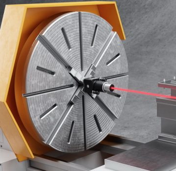
- 5-Axis Target to set up laser to spindle axis and to measure spindle squareness and straightness, especially on lathes and multi-turn machines. Squareness of cross-slide and machine axes can also be measured.
- Vertical and horizontal angular adjustments to precisely adjust the laser to the spindle’s axis of rotation or to align laser plane to reference points.
- Rechargeable LiPo battery runs the lasers for up to 8 hours.
- Small and rugged 4 x 2.9 x 1.7 in. (101 x 74 x 45 mm).
- Only needs 10 in. (254 mm) of space between spindle and tailstock or sub-spindle. For tighter spaces, see the L-703 Spindle Alignment System.
- Windows 7/8/10-based Machine Tool Geometry, MultiTurn10 and Lathe10 Software: Takes data for all axes of boring mills, machining centers and other machine tools, calculating straightness, flatness and squareness results and providing a comprehensive report on the alignment of the machine tool.