
Description
Hamar Laser’s new MultiTurn10 alignment software is a powerful tool for aligning the complex multiturn machine tools and was written to support our L-702SP 5-Axis Machine Tool & Spindle Alignment system. This comprehensive and easy-to-use program records data for all the machining axes of most types of multiturn type machine tools. It also checks the main spindle parallelism to the guideways and 4-axis alignment of the main spindle rotation axis to the sub-spindle axis. It can also be used on small CNC machining centers.
Applications
Applications include:
- Cylindrical Grinders
- Lathes
- Smaller Machining Centers
- Multi-Turn Machines
- Turning Centers
- Turret Lathes
Machine Geometry Measurement:
- Guideway flatness and straightness
- Axis pitch and yaw angular measurement – roll can also be measured
- Squareness of machine axes
- Squareness/parallelism of machine axes to rotation axes
- Main spindle-axis parallelism to subspindle or turret guideways
- Main spindle rotation-axis alignment to subspindle rotation axis in 4 axes
Features
Program Features include:
Easy 6-Step Process
 MultiTurn10 guides the user through the alignment with a 6-step process, designed to align the machine tool in the most efficient way. First the setup data is entered. Then the L-702SP is aligned to the main-spindle rotation axis. The guideways are checked for flatness & straightness and the parallelism of the main spindle axis to the guideways is calculated. If these geometries are out of spec, they need to be fixed first. Next, MultiTurn10 takes flatness and straightness data for the machining axes and subspindle axis. The results are tabulated into a summary of the alignment parameters. Then, the main spindle axis is checked for alignment to the subspindle in 4 axes. Finally, a printed report details the alignment of all the lathe geometries. Results can be plotted, saved, and exported to an Excel spreadsheet for further analysis.
Measure All the Axes of a Multiturn in Just 2 Setups
Two Setups are all that is needed to check all the axes for flatness, straightness, pitch, yaw, parallelism and squareness. With those setups, spindle-axis parallelism to the subspindle can also be checked in 4 axes.
Pitch, Roll and Yaw Angular Measurements
Using the angular-measuring lens of the T-1295/1296 targets, MultiTurn10 records the pitch and yaw angular errors of each axis without changing the setup. Switching to Scanning Mode, the targets can also measure roll of the main axes with an additional setup.
Easily Measure Main Spindle-Axis Parallelism to Guideways
 MultiTurn10 records the straightness data of the main bed and automatically calculates the guideway flatness/straightness and parallelism of the spindle axis to the bed. It can even check parallelism of the subspindle guideways if they are separated from the tailstock guideways.
Realtime 4-axis Data Display
The alignment displays the update with each adjustment in four axes: V-center, H-center, V-angle and H-angle. This allows the user to quickly correct misalignment errors and requires no calculations.
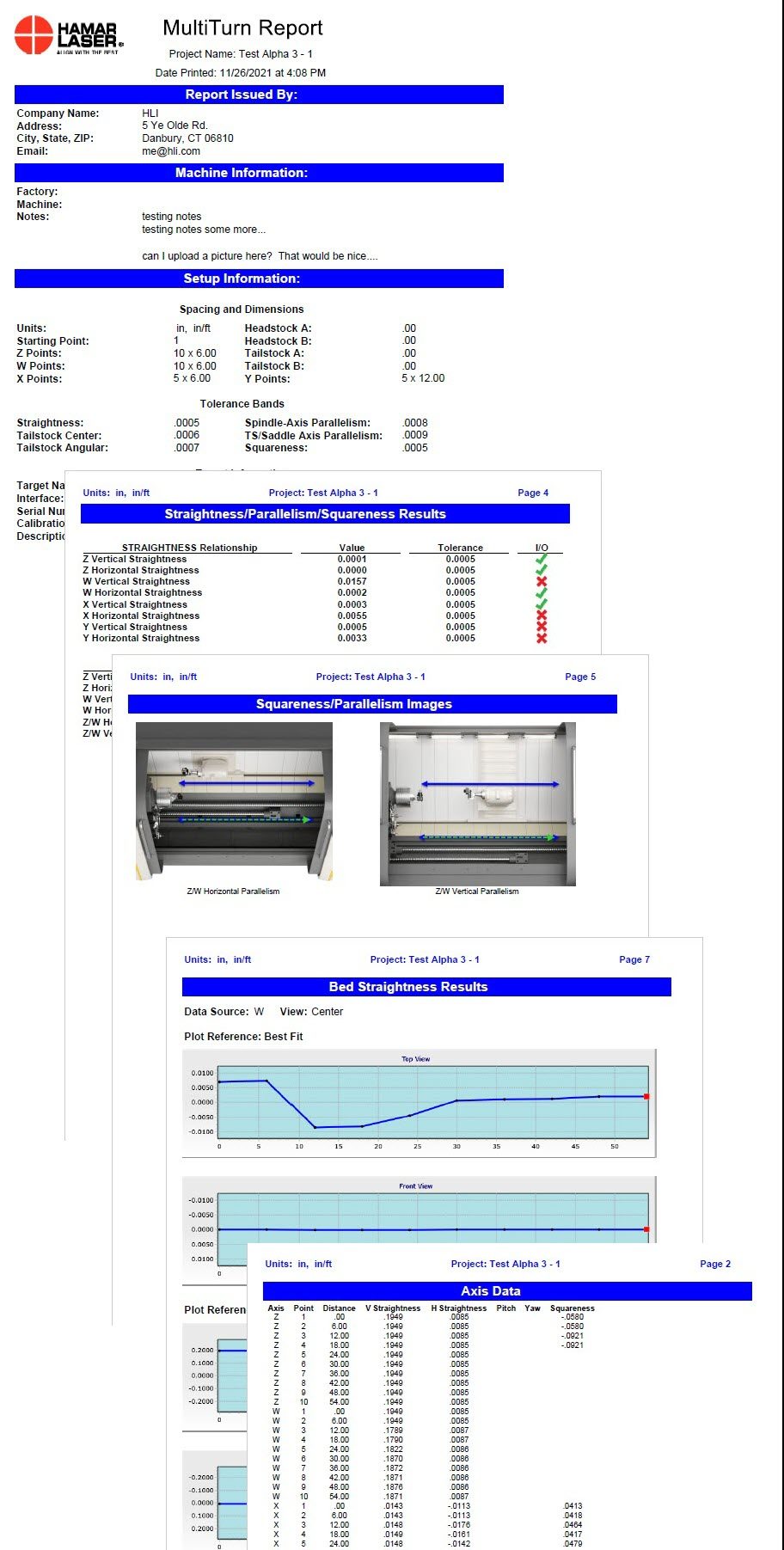
Report Generation
Reports can be customized to show the results relative to the laser or the guideway best-fit line, comments may be added, and the report can be printed with a summary, a graph of the vertical and horizontal straightness, comments and a table showing the recorded data
MultiTurn10 6-Step Process
 Step 1: Project setup
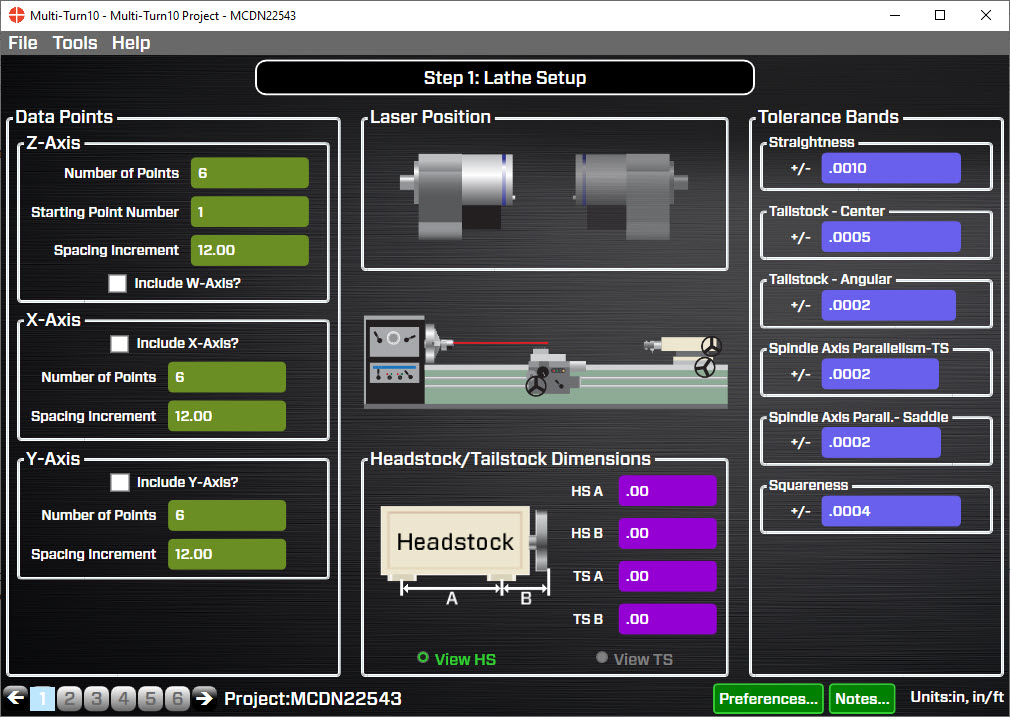
Choose the axes to check, the number of points to be recorded and enter the alignment tolerances. Also enter the dimensions of the main spindle housing. The dimensions are used to calculate shims when re-aligning the main spindle to the guideways. The alignment tolerances are automatically applied to the displays, results screen and graphs.
 Step 2: Qualify Laser
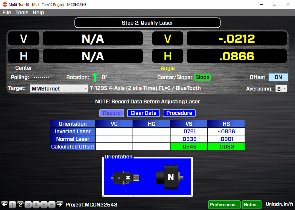
To check guideway parallelism, the laser needs to be aligned to the main rotation axis, which Step 2 is designed to do. By following the NORMIN procedure, where one set of data is recorded with the spindle/laser in the NORMal position and a second set is recorded with the spindle/laser in INverted position. Display offsets are automatically applied so the user zeros out (adjusts) the laser’s angular axes of adjustment to make the laser beam parallel to the spindle’s axis of rotation.
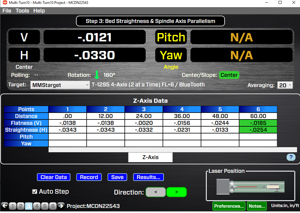
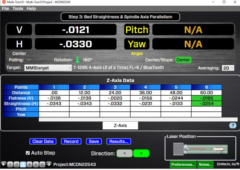 Step 3: Machine-Axis Straightness, Squareness and Spindle-Axis Parallelism

After qualifying the laser, flatness & straightness data is recorded for C2 (subspindle) and Z axes and the squareness to X and Y. A right-angle fixture is then used to align the laser to the Y axis, after which the Y axis straightness and squareness of Y to X and to Z. If pitch and yaw measurements are required they can be done by inserting the angular lens into the T-1295/T-1296 Target and recorded in Step 3. When finished, click the Results button to view the alignment data.
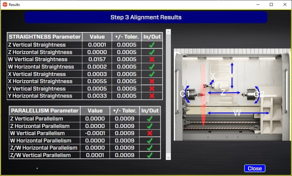 Step 3: Alignment Data Results
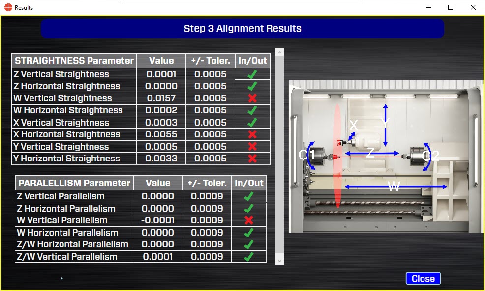
After taking data, click the Results button to view alignment results for:
- C1 spindle-axis parallelism to the C2 guideways.
- C2, X, Y and Z guideway flatness/straightness.
- Squareness of the X, Y and Z axes and also to C1 (main spindle)
- Parallelism of the C1 & C2 to Z
The result are tabulated in a table with a √or X displays if the data is in or out of tolerance, based on the tolerances entered in Step 1. A separate window shows the squarenesses between the axes with graphics to interpret the results.
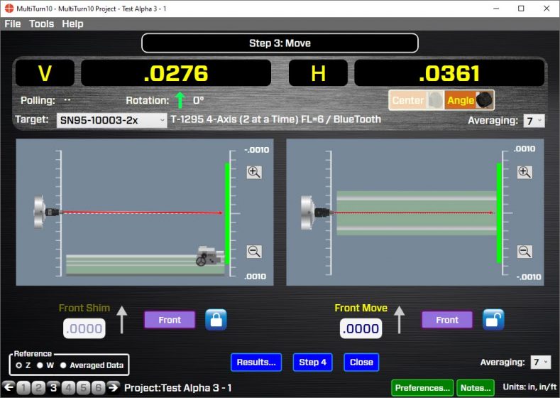 Step 3: Main Spindle-Axis Real -Time Alignment Screen

Click the Move button in Step 3 to open the Main Spindle-Axis Real Time Alignment Screen. In this screen, the headstock may be aligned to either the sub-spindle guideways or Z-Axis guideways. Shim values are calculated to align the headstock and a live angular display shows whether the alignment is in or out of tolerance.
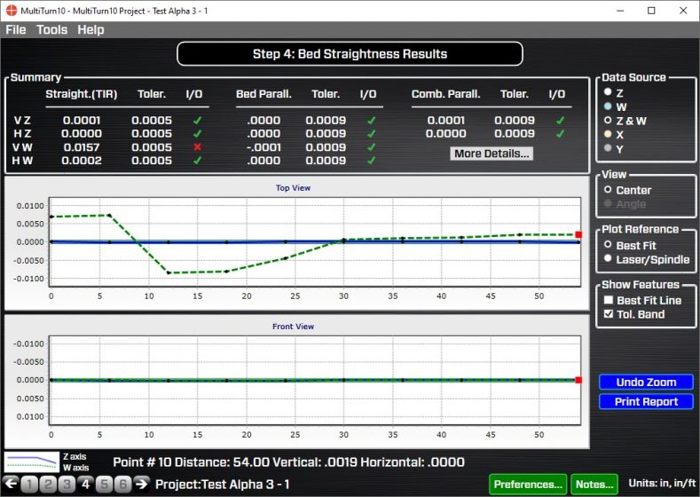 Step 4: Axis Straightness Results and Graph
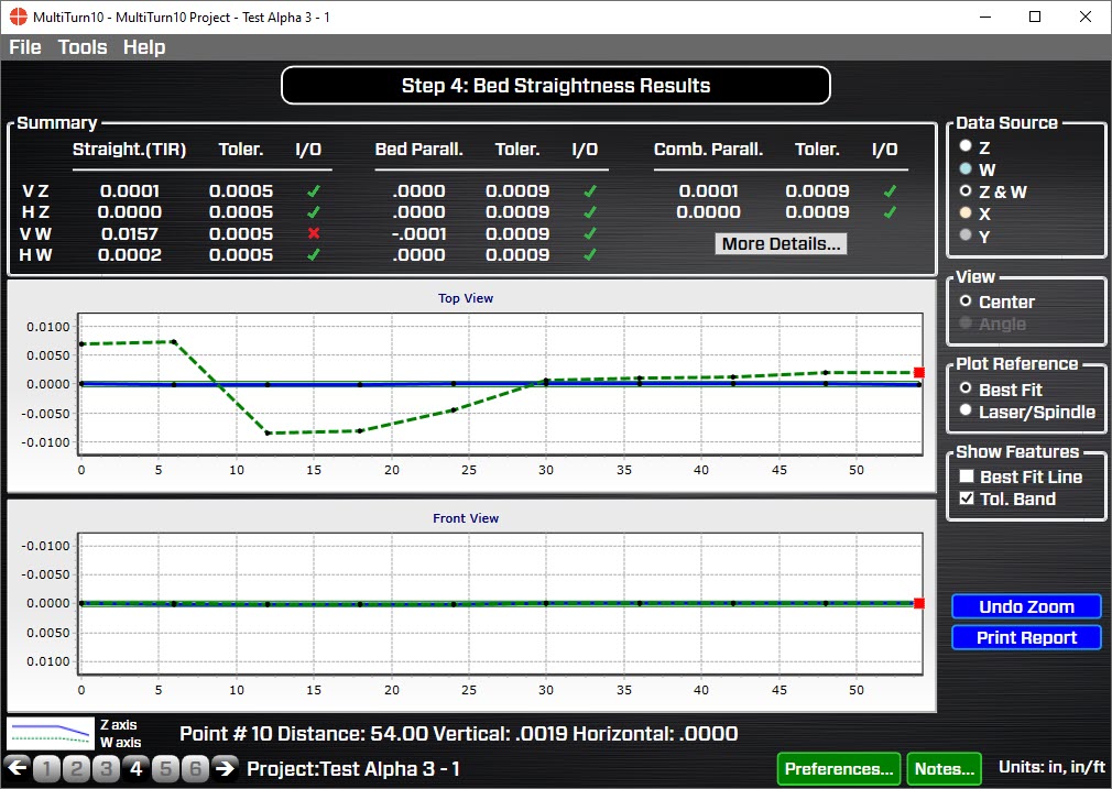
After recording data in Step 3, Step 4 calculates alignment results for:
- Flatness/straightness for each set of axis guideways
- The parallelism of the C1 (main spindle) axis to the guideways and Z-axis guideways
- The max pitch and yaw error for each axis
- The squareness between the axes
Results are displayed in the table and are compared against the tolerances defined in Step 1. Straightness is then plotted on a graph, showing whether the data is in or out of tolerance. The user may choose which set of data to plot and what reference to use: the laser or the least-squareness, best-fit line. Clicking a point on the graph displays the data for that point.
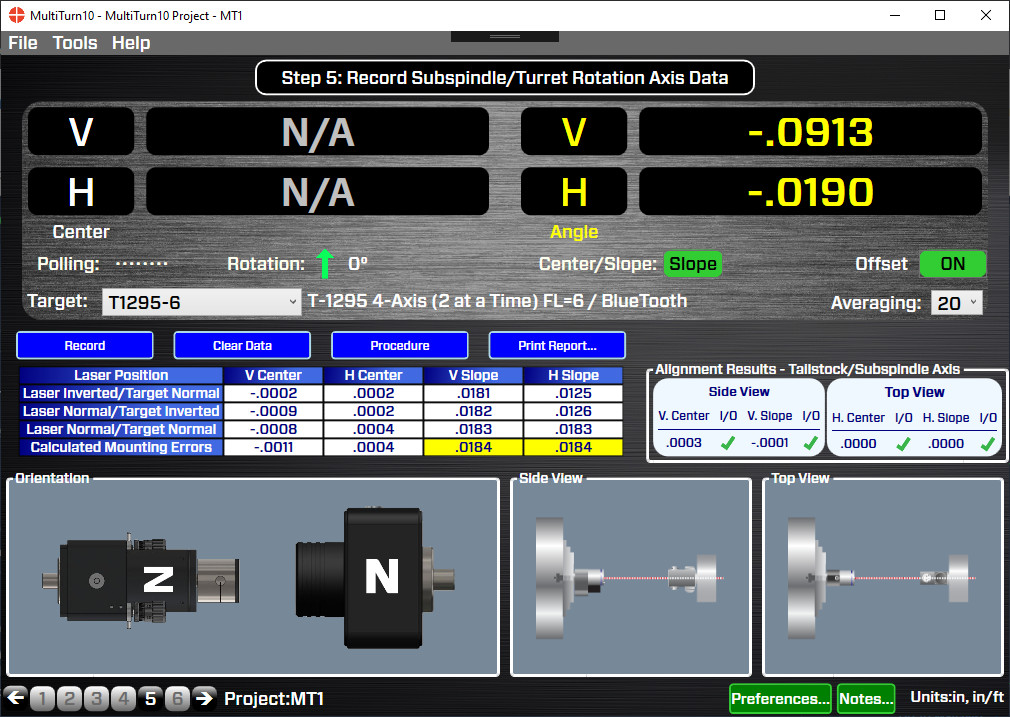
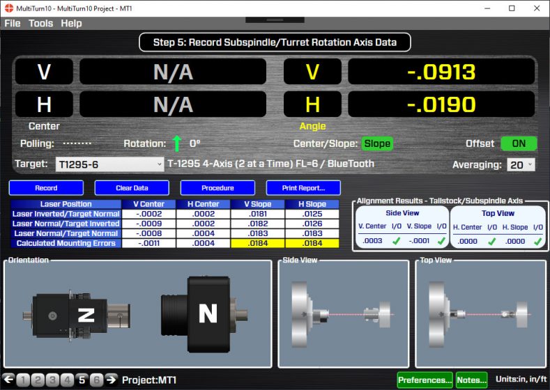 Step 5: Record Main Spindle-Sub-Spindle Rotation-Axis Data

After the main spindle axis has been aligned to the guideways, Step 5 is used to take data for the alignment sub-spindle’s rotation axis. It takes about 3 minutes to record the data and on- screen instructions guide you through the procedure. Once the data is recorded, alignment results are calculated and compared against the tolerance and spindle graphic illustrates the alignment. Display offsets are also automatically applied to the real-time display to show the alignment of the main spindle to the subspindle.
 Step 6: Main Spindle/Sub-Spindle Real -Time Alignment Screen
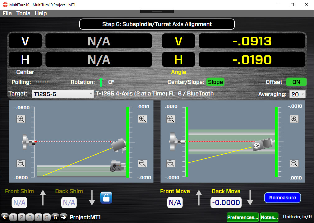
If the data recorded in Step 5 is out of tolerance, the misalignment can be fixed in the Step 6: Sub-Spindle/Turret Alignment screen. MultiTurn10 automatically applies display offsets so the real-time data display shows the actual alignment results. It also calculates the shims necessary to align the sub-spindle or turret. Live spindle graphics (vertical/side view and horizontal/top view) automatically update with each move, showing how the alignment is progressing. When the shim displays turn green, the alignment is complete.
Specifications
Drawings
- Call Us: +1-203-730-4600
- Email: sales@hamarlaser.com
- Website: www.hamarlaser.com