
Description
Hamar Laser’s Bore9 software records alignment (concentricity) data for up to 50 bores. It runs on Windows tablets and laptops for Win7, 8 and 10. It also measures straightness of cylinders and can measure diameter changes when used with our self-centering targets in Measure Mode. It supports all of Hamar’s past and present bore alignment equipment and features a step-by-step guide to help the user through the software.
Applications
Applications include:
- Engine Blocks
- Extruder Barrels
- Hydraulic Cylinders
- Large Bore Gun Barrels
- Printing Press Bearings
- Rotary Compressors
- Steam and Gas Turbines
Features
Program features include:
Built-in Step-by-Step Procedure
Bore9 guides the user through the alignment with a 5-step process, starting with Step 1- Bore Setup and ending with Step 5-Results. Results can be plotted, saved and also exported into an Excel spreadsheet for further analysis. Straightness data from up to 50 bores can be recorded.
Real-Time Data Display
The alignment displays the update in real time with each adjustment, allowing the user to quickly align the laser to end bores and correct misalignment errors.
Measures Concentricity/Alignment, Straightness and Bore Size
Bore alignment/concentricity is accomplished by bucking in the laser (making it parallel) to the end bores, and then moving the target from bore to bore to measure deviations from the end bores. By using the NORMIN error correction procedure, both the alignment of the bores and the diameter changes can be calculated automatically. All that is needed in an accurate diameter measurement of one of the reference bores.
Target Mounting Error Correction
Step 2-Target Mounting Error allows the user to follow our simple NORMIN procedure, removing target centering and fixturing errors to give the ultimate in bore alignment accuracy.
Comprehensive Plot Capabilities
The data can be plotted in an X-Y or concentricity format. The datum reference can be changed from: i) end bores, ii) selected bore numbers, iii) the laser beam or iv) a “Best Fit” line. The data for each point is recalculated automatically based upon which references are chosen.
Other Plotting Features
Additional features include the ability to zoom in and out of the graph area, to change direction when recording data, to select the target orientation when performing the NORMIN procedure and to automatically move from one point to be measured to the next.
Report Generation
Reports can be customized to the 4 different bore references, comments may be added, and the report can be printed with a summary, a graph of the concentricity, vertical and horizontal straightness, comments and a table showing the recorded data.
Program Features
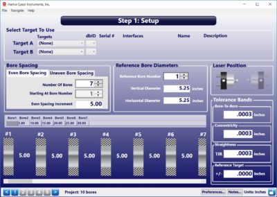
Step 1: Set up Bore9
The Bore9 Setup Screen prompts for the target(s) to use, the number of targets, even or uneven bore spacing, the number of points to be measured, the reference bore diameter, the laser position and tolerance bands (overall, bore-to-bore and reference target).
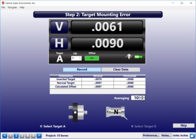
Step 2: Target Mounting Error
The Target Mounting Error Screen uses NORMIN procedure to determine mounting errors in the target and bore adapter and automatically adjusts the display to remove the error from the readings. The user will be required to take 2 data points: 1) with the target in the NORMal position; and 2) with the target in the INverted position. The software calculates the mounting error and then applies it to the displayed and recorded data to remove the mounting error from all data points. This is a global target offset and is applied to all data, but it can be toggled on and off as needed.
Step 3: Buckin
Buckin (laser setup) calculates set points for making a laser parallel to 2 reference points, usually the end bores. The Buckin Wizard guides you through the Buckin process for both internally mounted lasers (such as the L-708 Laser with the A-514 Self-Centering Adapters or any laser mounted directly in a spindle) and externally mounted lasers (such as the L- 705/L-706/L-708 with the L-111 Laser Stand and L-102 Beam Translator).
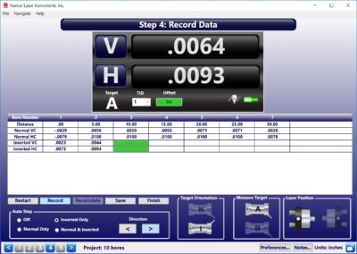
Step 4: Record Data
Data may be recorded with Auto Step, which automatically advances the cursor to the next data point to be recorded. To record data, the user selects the desired Auto Step method and inserts the target/adapter into the first bore. He then clicks Record or presses the spacebar to record the data point. The target/adapter is moved into the second bore and the recording process is repeated until all data has been taken.
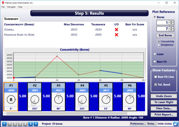
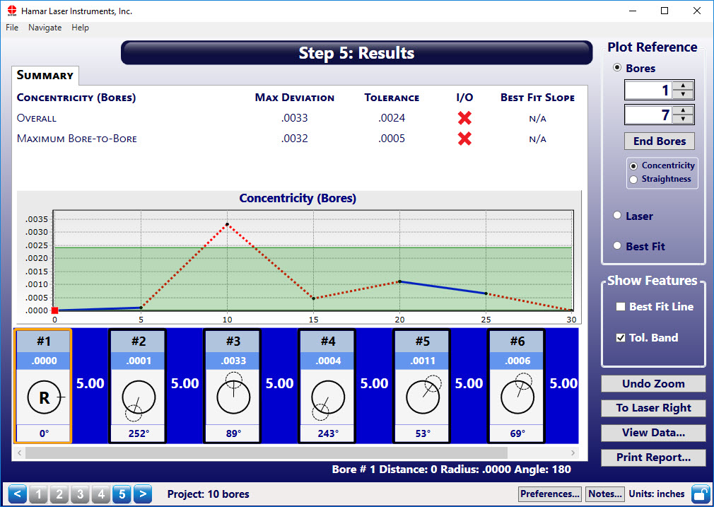
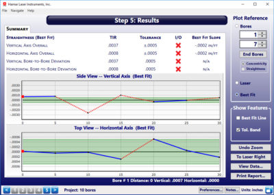
Step 5: Results
Once data is taken, a plot of the data is generated in Step 5: Results. The Plot Reference can be changed to reflect the following:
Concentricity – Shows the alignment of the bores in a concentricity format relative to the end bores. The angular direction of the alignment value is shown in the graphic below the graph.
Bore Numbers – Shows the alignment of the bores relative to the selected bore numbers. This view makes the designated bore numbers the zero point and plots the positions of the remaining bores in relation to selected bore numbers
Best Fit – Shows the X-Y alignment of the bores relative to the Best-Fit line rather than to the laser beam. To calculate the Best-Fit line, a least-squares, best-fit algorithm is used to find a line that “best fits” the raw data. It is especially useful because it removes any excess error in the data from the laser beam not being perfectly aligned to the end bores, so laser setup is faster and easier since the laser beam does not have to be exactly centered to the end bores to get accurate straightness measurements.
Laser – Shows the misalignment of the bores relative to the laser beam (raw data). A dashed black line indicates the Best-Fit line.

Report
Add company contact information and notes, select the type of graph you want and the plot bore reference and the report will be customized to the selections. The report can be printed to PDF and emailed.

Specifications
Drawings
- Call Us: +1-203-730-4600
- Email: sales@hamarlaser.com
- Website: www.hamarlaser.com