
Description
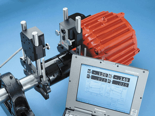
The S-640 Coupling Laser Alignment System has been designed for those with limited budgets but with high accuracy needs. It uses a single diode laser with the T-266 4-Axis Coupling Target and has been a workhorse for coupling alignment since it was introduced in 1992. It has newly designed brackets and computer interface that is 4 times smaller and is 5 times more accurate than the previous model. It also uses our new Windows-based Coupling4 software, featuring large, color graphics and color reports.
L-740 Laser
The L-740 laser is a low powered, single-beam visible-light Class II laser. It operates on a 9V rechargeable battery that lasts up to 8 hours on a single charge. The visible light requires no special viewing devices, allowing easy setup and rough alignment. It features an on/off switch that covers the optics when not in use.
T-266 Target
The T-266 is a 4-axis target that simultaneously displays horizontal and vertical center and angle readings. It also has an internal rotation sensor that automatically tells the software what clock position the laser is in. It produces accurate results with as little as 90 degrees of rotation. A metal shield protects the target optics when not in use.
R-358 Computer Interface
The R-358 computer interface, our newest generation of interfaces, provides high accuracy (.00002” or 0.0005 mm resolution) for downloading live target data into the Couple4 Software. It attaches to the computer with an RS-232 cable, is powered by a lithium ion battery for long life and usage, and automatically turns on when the target starts taking measurements. An AC adapter/charger is provided, and the unit features “charging” and “power” LED indicators.
A-907 Bracket Set
These aluminum and stainless steel dual-post mounting brackets feature quick-set speed nuts for nearly instant setup and can accommodate shaft diameters from 0.5″ to 5″ (12.7 mm to 127 mm) with standard chainless bracket, and shaft diameters from 5″ to 12″ (127 mm to 305 mm) the with chain attachment. With extra chain links it can accommodate up to 18″ (457 mm) of shaft diameter. It has built-in magnets for shafts with large flanges, such as turbine rotor couplings.
Applications
Features
- Target provides 4-axis dynamic display of shims and moves.
- Uses windows-based software with large, color graphics to display misalignment.
- Target has a resolution of .00002″ (0.0005 mm) for center and .00012″/ft (0.01 mm/M) for angle.
- Uses quick-set brackets, for 0.5″ to 12″ (127 mm to 305 mm) diameter shafts, to mount to shafts.
- System provides coupled or uncoupled shaft alignment capabilities.
- System has vertical pump capability.
Software has soft-foot routine. - Target rotation sensor automatically adjusts screen for clock position
- Portable/rugged
- Up to 30-foot (9.1 M) operational range between laser and target.
- Reports can be generated in the field with optional PCMCIA Portable color printer.
Specifications
.00012 in/ft (.01 mm/M) angular
± .150 in. (3.81mm) center
Link Chain Clamp Set: 5 in. diameter to 12 in. diameter (101.6 mm 304.8 mm).
Can accommodate shafts up to 18 in. diameter (475.2 mm) by adding additional chain.
(4) 12 in. long (304.8 mm)
Drawings
- Call Us: +1-203-730-4600
- Email: sales@hamarlaser.com
- Website: www.hamarlaser.com