
Description
Spindle8 is the culmination of nearly 10 years of experience with transfer-line spindle alignments. It analyzes and aligns single or dual spindles, providing 4-axis, live data that shows changes in alignment as they are made. It is designed to work with our L-700 Spindle Alignment Laser System and runs on Windows® PC’s and laptops.
Applications
Features
Features of the Spindle8 program include:
- Step-through checklist – Spindle8 is based on an easy-to-follow, 5-step checklist, with illustrations and step-by-step instructions that prompt the user for information to complete each stage of spindle alignment.
- Single or dual-spindle capability – The spindle alignment system aligns single spindles or dual-spindle heads. To align dual spindles, 2 L-700 systems are required. The data for each target can be recorded separately or simultaneously.
- Real-time alignment displays – Spindle8 shows alignment changes as they are made, using large, color graphics.
- Automatic shim/move calculations – The software speeds up alignment by automatically calculating shim and move values.
- User-definable tolerances – Alignment tolerances can be set by the user. Shim-value displays automatically change to “In Tolerance” when specified tolerances are achieved.
- Comprehensive reporting function – Generates and saves reports that include collected data and graphical views of the alignment. Reports can be modified and printed.
- Random data mode – Random data mode allows the program to run without hardware for training or user familiarization prior to performing an actual alignment.
Program Features
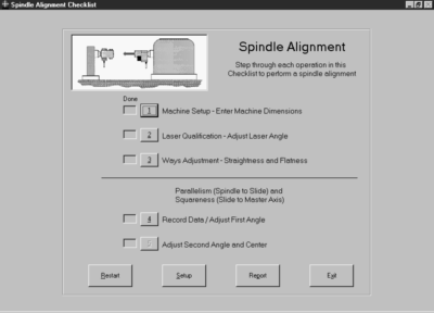
CHECKLIST-BASED SOFTWARE FOR EASE OF USE
Spindle8 is based on a 5-step checklist, with illustrations and step-by-step instructions prompting the user for information to complete each stage of spindle alignment.
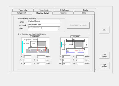
STEP 1: MACHINE SETUP
The user is queried for machine dimensions at specified points, all of which are clearly labeled. If the alignment involves dual spindles, that is specified in this step. Other information, such as alignment tolerances, target setup, units of measure, and company information, is also entered by clicking on the various tabs of the setup screen. All settings can be saved or loaded from previously saved files.
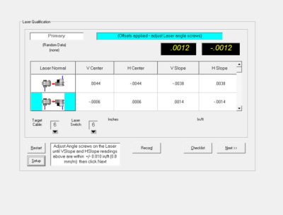
STEP 2: LASER QUALIFICATION
Using Hamar Laser’s NORMIN method, the software determines laser mounting errors in Step 2. Each position of the laser is illustrated on screen as the user makes the appropriate rotations and records the readings to determine the mounting errors.
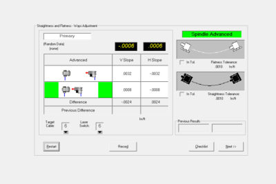
STEP 3: GUIDEWAY STRAIGHTNESS
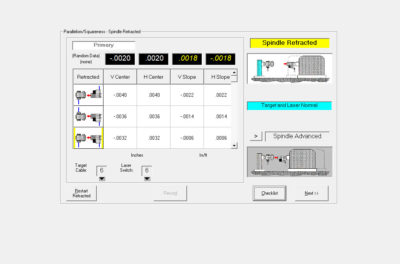
This step provides a coarse check of the straightness and flatness of the spindle-box ways to verify that they are in tolerance. Readings are taken with the spindle head in both retracted and advanced positions and the user is advised how to adjust the ways to bring them into specified tolerances.
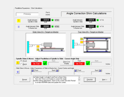
STEP 4: RECORD DATA/ADJUST FIRST ANGLE
This step determines if the spindle axis of rotation is parallel to the spindle-box ways and colinear with the master-part centerline to the specified tolerances. The software allows the user to choose which angular error to fix first: i) the ways or (ii) the wingbase. A live, 2-axis data display shows angular adjustments as they are made and provides shim values.
![]()
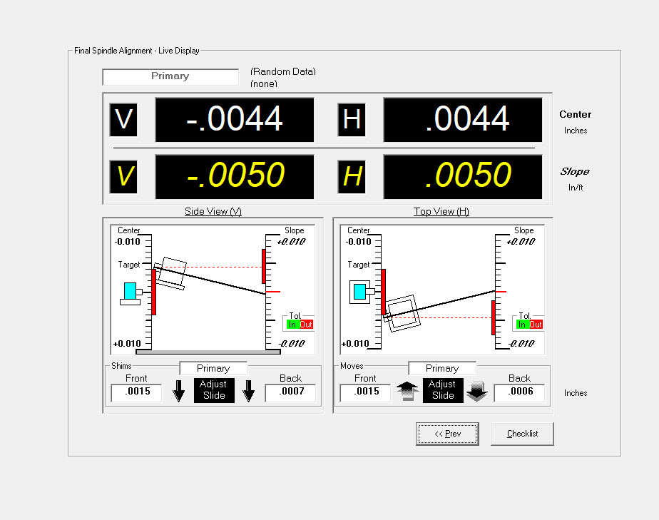
STEP 5: ADJUST SECOND ANGLE AND CENTER
Step 5 provides a live, 4-axis display for adjusting center and slope of the whole wingbase/spindle- box assembly. Shim and move values are displayed on screen, and the display indicates when specified tolerances have been satisfied.
GENERATE ALIGNMENT REPORTS
Once the alignment has been completed, a report can be generated that includes collected data and graphical views of the alignment. These reports can be saved, modified and printed.
Specifications
Drawings
- Call Us: +1-203-730-4600
- Email: sales@hamarlaser.com
- Website: www.hamarlaser.com